
Eureka
For R&D, Eureka makes reading and utilizing patents & technical documents easy.
Eureka AIR
Designed for self-driven R&D workflows. Generate viable solutions, solve complex R&D challenges, empower your innovation with AI.

Eureka Materials
Designed for material experts only. Revolutionize your material R&D, from search, analyze, to developing new materials.

TechResearch
Generate reliable direction feasibility study reports for your R&D in just a few steps.

TechSeek
Discover and master advanced knowledge NOW. Basics, ideas, possibilities, all at once.

TechMind
As an expert in R&D Theories, TechMind can generates customized viable solutions instantly.

TechRisk
Analyze your overall solution with one click, know your potential R&D risks in advance.

TechMonitor
Get weekly tech updates, stay abreast of the latest tech innovations and key insights.
System and method for non-invasive determination of optimal orientation of an implantable sensing device
- Summary
- Abstract
- Description
- Claims
- Application Information
AI Technical Summary
Problems solved by technology
Method used
Image

Examples
embodiment 1
Standard ECG Electrodes
In the most simple form of the invention, a standard ECG Monitoring System can be used with the standard electrodes and electrode preparation of the skin. The electrodes are placed in orthogonal patterns of the proper electrode spacing over each candidate implant site as described in the above paragraph per FIG. 9.
Orthogonal measurements are taken over each candidate implant site, illustrated as locations 1, 2, and 3, on a patient's body. Two or more electrodes are used to take the measures. The current example illustrates the use of three electrodes being used in an orthogonal pattern.
According to one method of the current invention, signal amplitudes may be noted using the orthogonally-positioned electrodes. It may be assumed a similar implant orientation will result in a similar signal reception. Movement of the electrodes may be performed until a satisfactory signal reading is obtained at a given location and orientation.
For a more exact orientation to pro...
embodiment 2
Hand-Held Device with Fixed Electrode Probes
FIG. 10A is a diagram of a handheld device uses to determine optimal orientation of an implantable device. This device 90, which is similar to a hand-held emergency heart monitor provided by several manufacturers, can be used to probe the surface locations and orthogonal orientations that are desired in order to find the optimum orientation. Signal measurements may be performed with two or more electrodes residing on at least one surface of the device in a manner to be discussed below. This device will be customized with electrode size and spacing that matches a particular associated implantable device. This is necessary to provide accurate measurements. The device of FIG. 10A may display the ECG on an attached recording device or display, or on a built-in display such as an LCD monitor. The exemplary embodiment includes a customized hand-held portable ECG monitor of the type commercially available from the Micromedical Industries Inc. of ...
embodiment 3
Electrode Patch
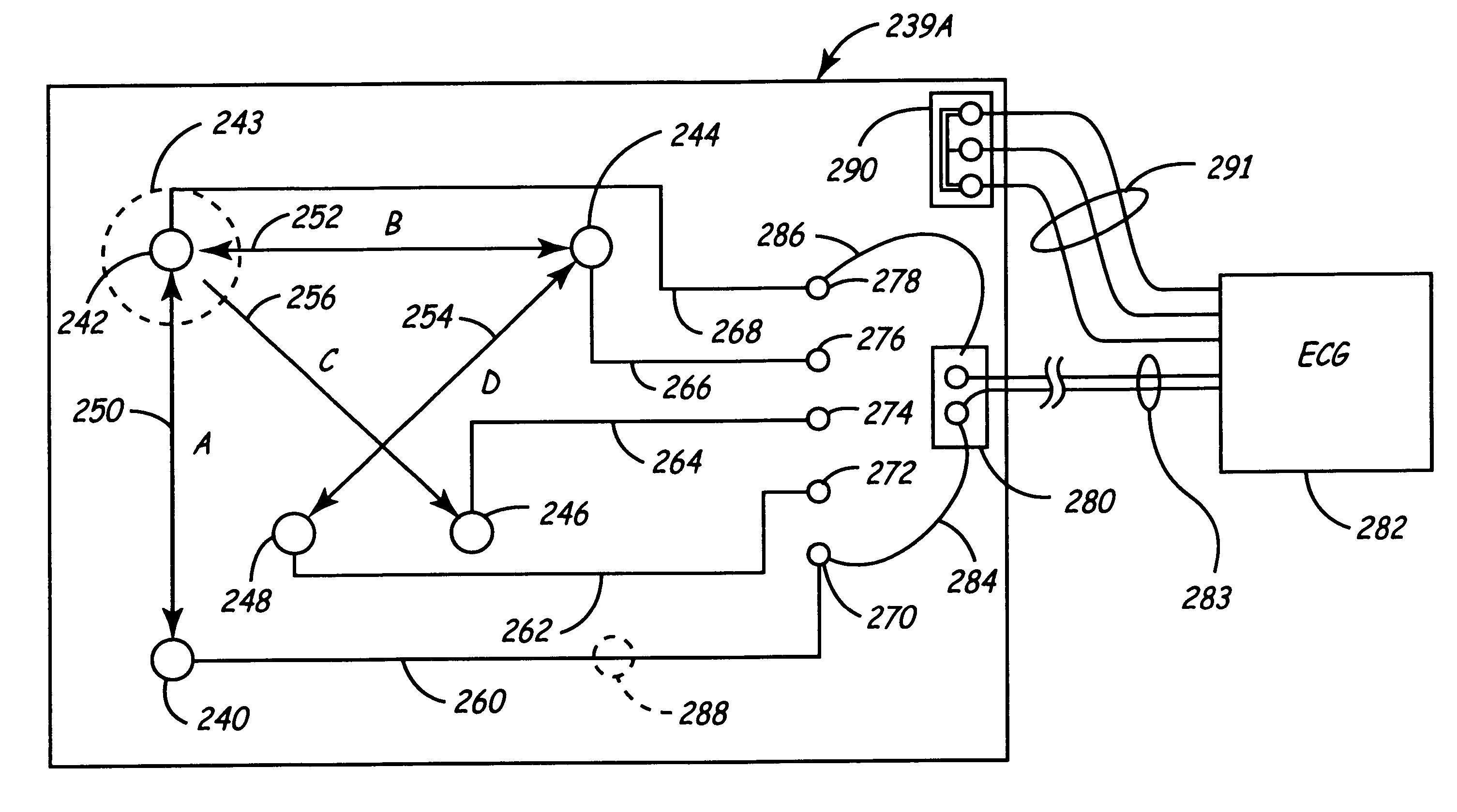
FIG. 13 is a diagram of an embodiment of the current invention that includes an electrode patch 239A. This embodiment includes a thin, flexible patch of the type that is commercially available for use with surface electrodes used when taking ECG measurements. Such patches may be made of many types of plastic, for example. Multiple electrodes 240 through 248 are coupled to the patch. Each electrode is provided with a central conductor, and a larger surrounding conductive surface area 243 (shown dashed) for contacting a patient's skin. Although this surface area 243 is shown only for electrode 242, it is understood that such a surface area is provided for all other electrodes 240 through 248.
In one embodiment, the electrodes are positioned so that various electrode pairs are spaced at substantially the same distance. For example, the current embodiment includes the electrode pairs indicated by arrows 250, 252, 254, and 256. The distance between the electrodes in each of...
PUM
 Abstract
Description
Claims
Application Information
 - R&D Engineer
- R&D Manager
- IP Professional
- Industry Leading Data Capabilities
- Powerful AI technology
- Patent DNA Extraction
Browse by: Latest US Patents, China's latest patents, Technical Efficacy Thesaurus, Application Domain, Technology Topic, Popular Technical Reports.
© 2024 PatSnap. All rights reserved.Legal|Privacy policy|Modern Slavery Act Transparency Statement|Sitemap|About US| Contact US: help@patsnap.com