Bundling device for a length of line type material

a technology of a bundler and a material, applied in the direction of machine supports, flexible container closures, snap fasteners, etc., can solve the problems of decreasing the life expectancy of a line, unable to be easily lost, and devices that have proved inadequate for field us

Inactive Publication Date: 2002-12-31
FRAZIER MARK
View PDF20 Cites 65 Cited by
  • Summary
  • Abstract
  • Description
  • Claims
  • Application Information

AI Technical Summary

Problems solved by technology

As well as being difficult, unreliable, and time consuming this puts a strain on the end of the line set thus decreasing the life expectancy of a line.
Early bundling devices consisted of a short length of string or rope to tie around a bundle of line to hold the line in an coiled loop, this bundled the line but did not separately hold a segmented portion of line and was therefor able to become lost easily.
These devices have proven themselves inadequate for field use due to their bulky design and limited range of line type material in which they may hold.
Some other less bulky inventions such as Kaplan U.S. Pat. No. 4,096,863, Kaplan U.S. Pat. No. 5,920,965 and Kaldor U.S. Pat. No. 5,745,958 were invented but still these devices were inadequate due to their limited range of line type material in which they may hold.
Inventions such as, Hasslinger U.S. Pat. No. 4,088,136, Hunt U.S. Pat. No. 5,075,932, Lyons U.S. Pat. No. 5,881,436, Hahn U.S. Pat. No. 5,142,743 Trethewey U.S. Pat. No. 5,548,871, Tolan U.S. Pat. No. 5,802,676, Denaro U.S. Pat. No. 5,031,282, and Reed U.S. Pat. No. 5,168,603 address the issue of disposing the device to a segmented portion of the line type material and incorporate a wide range of line type material in which they may hold, but they do not address the issue of firmly disposing the device to the line type material.
Thus compromising the integrity of the device by the device being able to move laterally about the line type material.
A device such as Fennell U.S. Pat. No. 4,700,432 addresses the issue of firmly disposing the device to the line type material but this device uses a tie that is difficult to release from the line type material therefor reducing the life of the tie and making it necessary to replace the tie from time to time.

Method used


Image

  • Bundling device for a length of line type material
  • Bundling device for a length of line type material
  • Bundling device for a length of line type material

Examples


Embodiment Construction

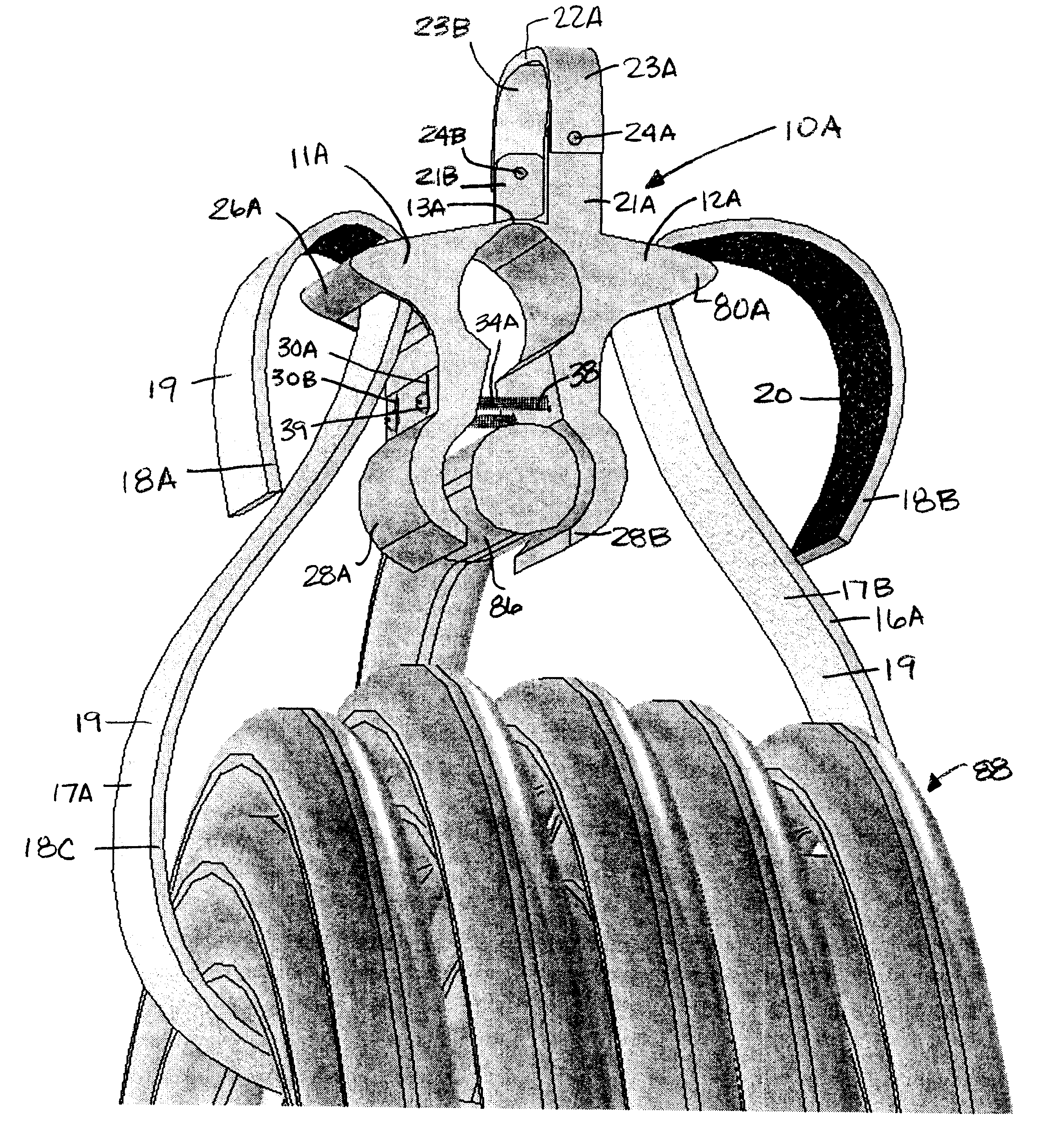
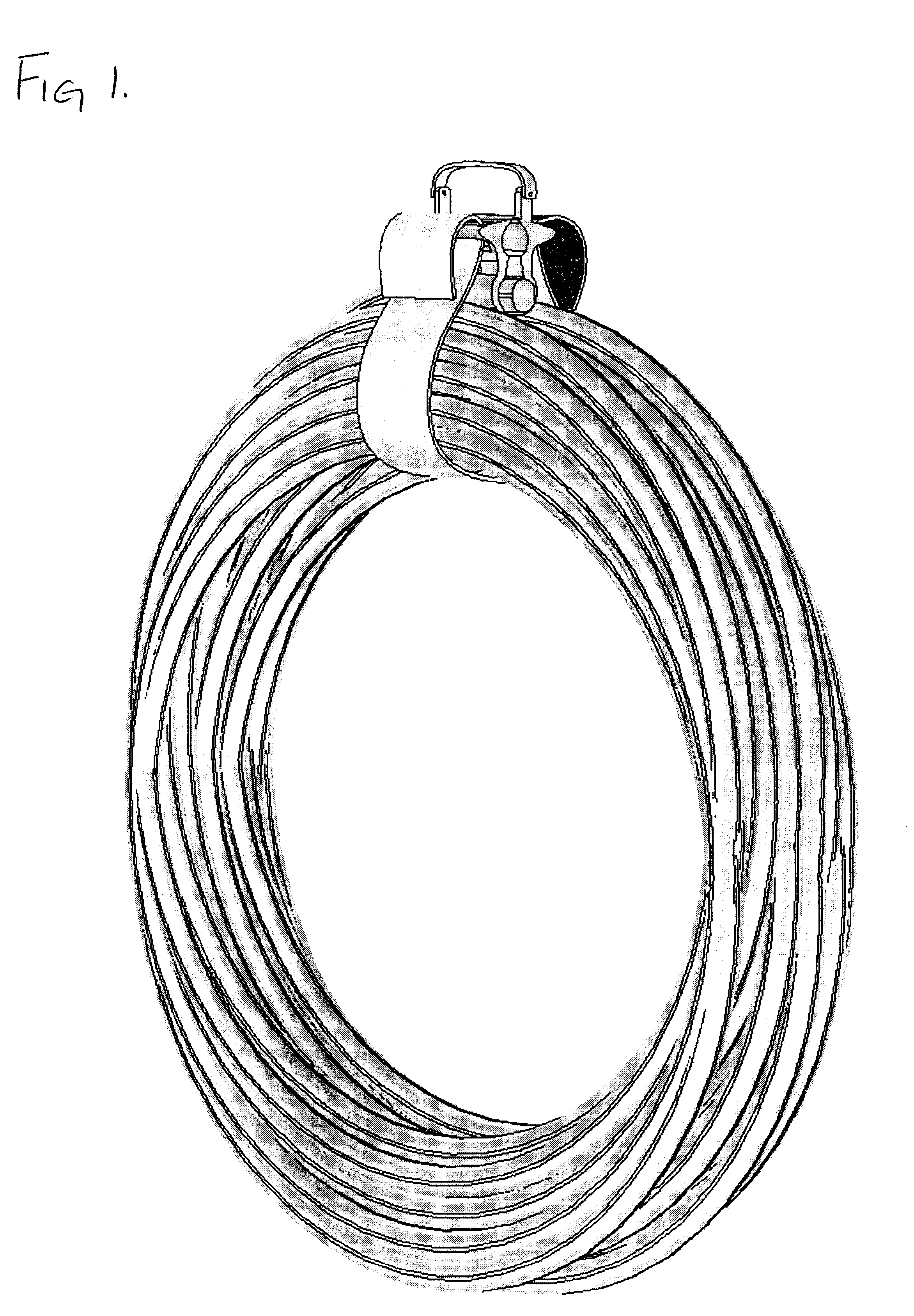
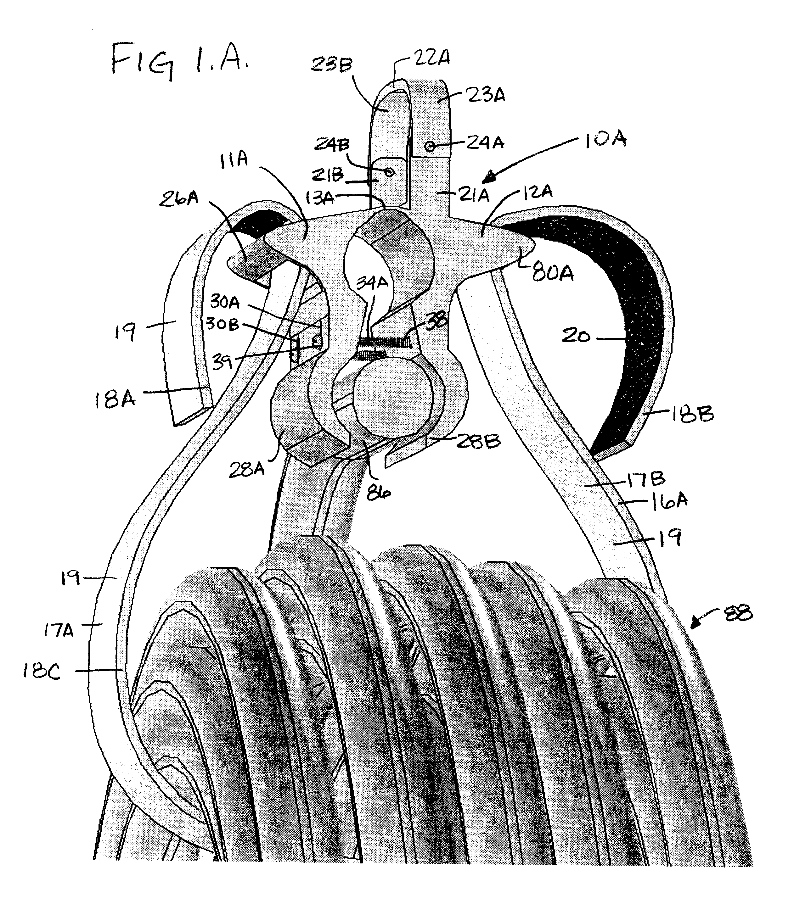
A preferred embodiment of the bundling device of the present invention is illustrated in FIGS. 1A, 1B, and 1C. The bundling device has a body 10A that is formed with a plastic material by using a process called injector molding. Body 10A is formed with a body portion one 11A and a body portion two 12A that are joined together at a bending point 13A. Bending point 13A is disposed at the top of body 10A.

Body 10A is formed with a mounting bracket 21A and a mounting bracket 21B formed on top of body portion two 12A. Mounting bracket 21A and mounting bracket 21B and a hanger strap 22A are disposed above body 10A so as to create a bundling strap pass through 96 for a bundling strap 16A. The width of bundling strap pass through 96 is greater than the width of bundling strap 16A. The height of bundling strap pass through 96 is greater than the height of bundling strap 16A. Hanger strap 22A is comprised of a flexible nylon fabric material. A hanger strap end one 23A is mounted to mounting br...


PUM


Abstract

A bundling device designed for ideal use in the field that it is designed to aid in the management, storage, and protection of a wide range of a line type material. Bundling device is designed to be easy to operate, inexpensive to produce, compact, and durable. Bundling device comprising of a reusable body that is formed so as to be firmly disposed to a segmented portion of line type material. Bundling device comprises of a bundling strap designed so that it may effectively hold a wide range of personally sized coiled lengths of line type material. Body may be designed so that it may be firmly disposed to an electrical extension cord set, or an electrical extension cord, or a coaxial cable, or a rope, or a set of battery jumper cables, or a tow strap, or a like line type material. Bundling device may also be incorporated into an existing device that is already firmly disposed to a segmented portion of line type material such as an electrical extension cord plug, or an electrical extension cord strain relief.

Description

BACKGROUND--FIELD OF INVENTIONThis invention relates to a bundling device that is comprising of a body that is designed to be firmly disposed to a segmented portion of line type material. Where bundling device is also comprising of a bundling strap designed to hold a personally sized coiled length of line type material such as an, electric extension cord, coaxial cable, tube, hose, rope, battery jumper cable, strap, or the like of, in a coiled arrangement to the bundling device.BACKGROUND--DESCRIPTION OF PRIOR ARTMany line type materials such as cords, cables, ropes and the like of necessitate an orderly arrangement for both storage and safety purposes. The most common arrangement of these materials is in a coiled loop. Before a device was invented the solution was to wrap one end of the line around the coiled line, then tie up one end of the line to itself. As well as being difficult, unreliable, and time consuming this puts a strain on the end of the line set thus decreasing the l...

Claims


Application Information

Patent Timeline
Patent Type & Authority Patents(United States)
IPC IPC(8): F16L3/22F16L3/233B65H75/36
CPCB65H75/366F16L3/2336B65H2402/412Y10T24/2708Y10T24/15
Inventor FRAZIER, MARK
Owner FRAZIER MARK
Why Eureka
Try Eureka