
Microcontrolled ballast compatible with different types of gas discharge lamps and associated methods

a technology of gas discharge lamps and microcontrollers, which is applied in the direction of instruments, light sources, electrical devices, etc., can solve the problems of reducing the life of lamps, and achieve the effect of increasing the life of lamps

Inactive Publication Date: 2002-12-31
STMICROELECTRONICS SRL
View PDF2 Cites 25 Cited by
  • Summary
  • Abstract
  • Description
  • Claims
  • Application Information

AI Technical Summary

Benefits of technology

The ballast preferably further comprises a control circuit for causing the power supply to provide the desired operating parameters based upon the type of gas discharge lamp. Since the desired operating parameters are applied to the gas discharge lamp, the life of the lamp is increased. The ballast according to the present invention is thus compatible with different types of gas discharge lamps, such as lamps of different wattages.

Problems solved by technology

An excess voltage applied to a gas discharge lamp may decrease the life of the lamp.

Method used


Image

  • Microcontrolled ballast compatible with different types of gas discharge lamps and associated methods
  • Microcontrolled ballast compatible with different types of gas discharge lamps and associated methods
  • Microcontrolled ballast compatible with different types of gas discharge lamps and associated methods

Examples


Embodiment Construction

The present invention will now be described more fully hereinafter with reference to the accompanying drawings, in which preferred embodiments of the invention are shown. This invention may, however, be embodied in many different forms and should not be construed as limited to the embodiments set forth herein. Rather, these embodiments are provided so that this disclosure will be thorough and complete, and will fully convey the scope of the invention to those skilled in the art. Like numbers refer to like elements throughout. The dimensions of layers and regions may be exaggerated in the figures for greater clarity.

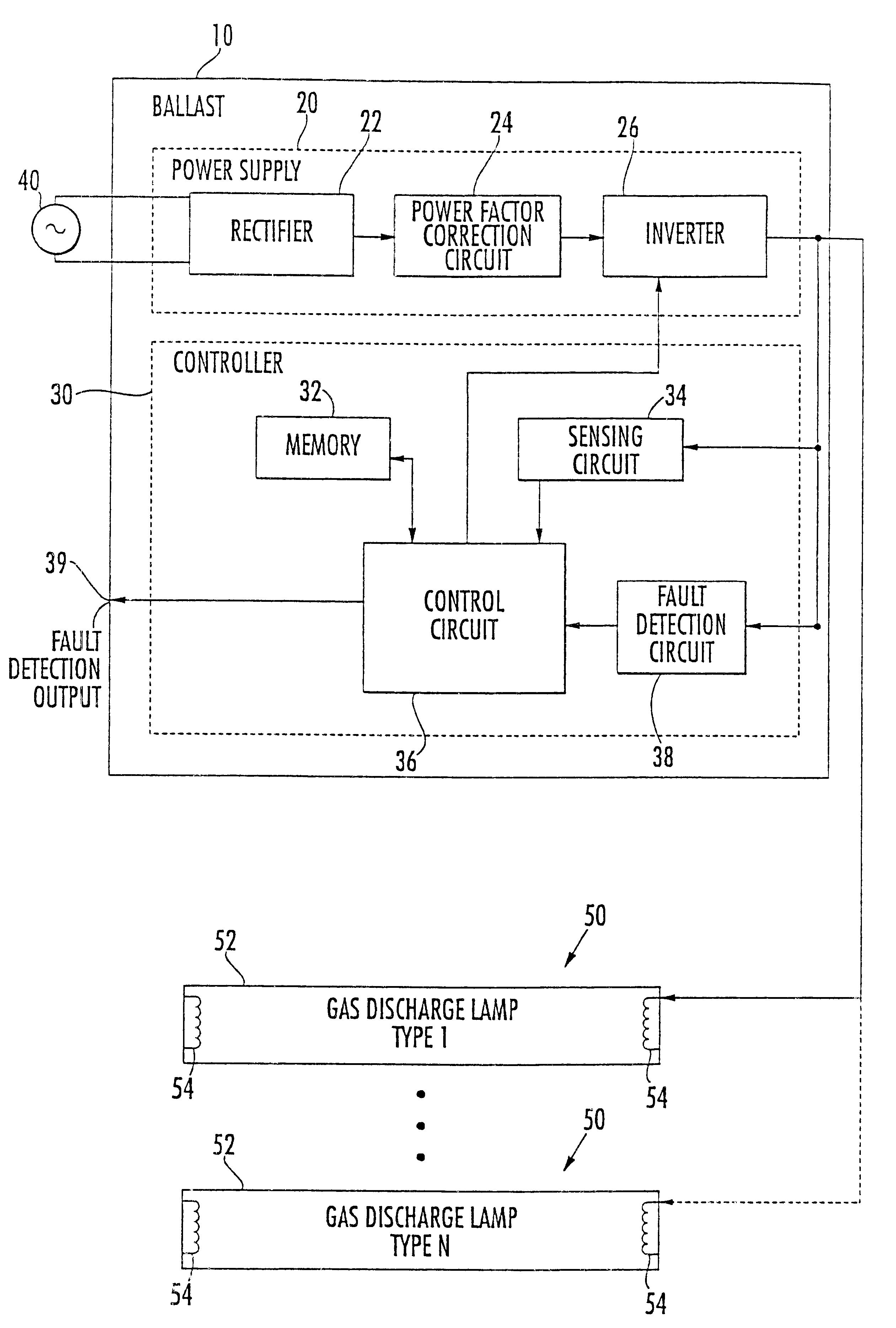
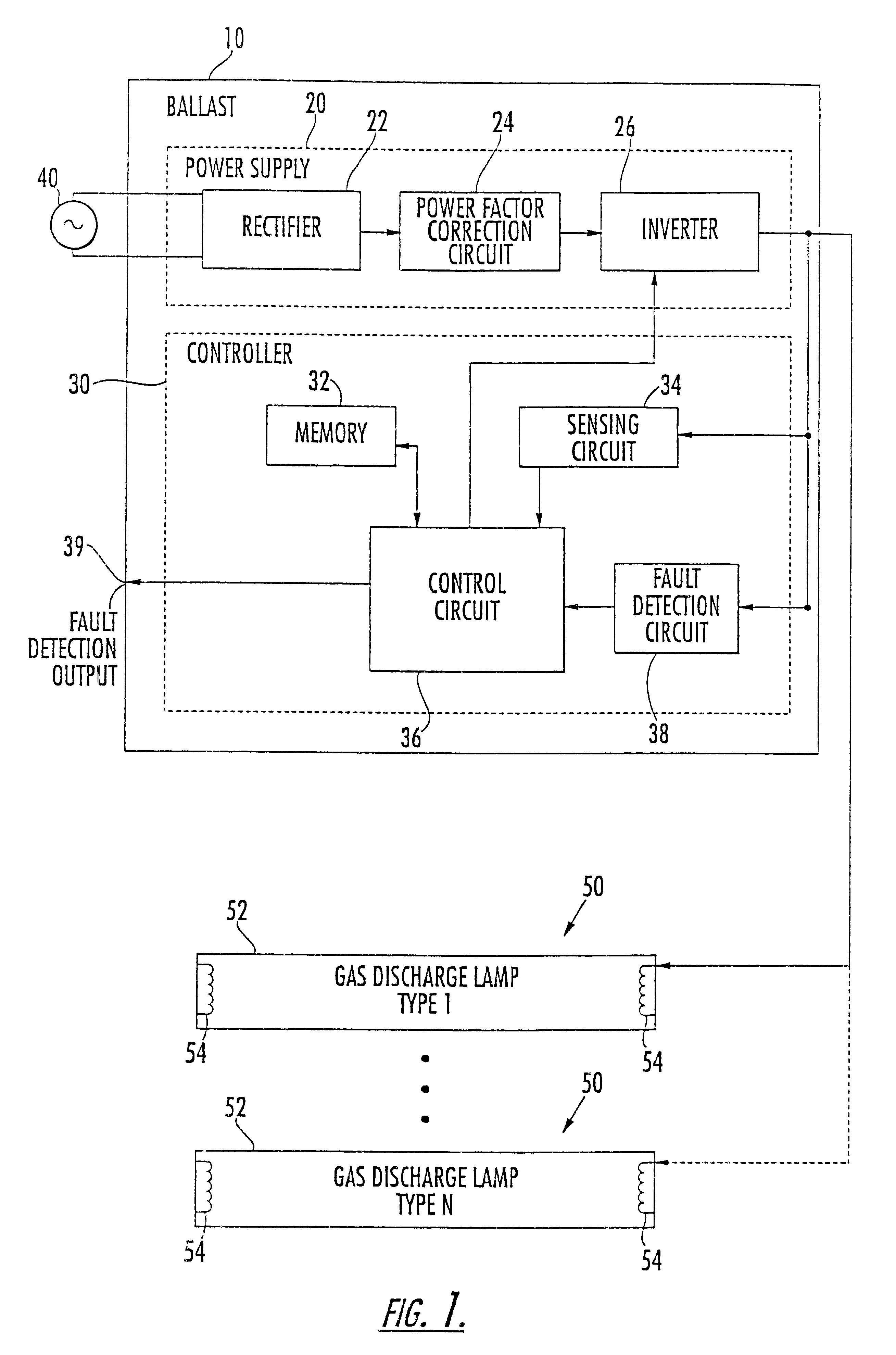
Referring initially to FIG. 1, a ballast 10 compatible with different types of gas discharge lamps 50 in accordance with the present invention will now be described. The ballast 10 comprises a power supply 20 and a controller 30 connected thereto. The ballast 10 is connected to an alternating current (AC) source 40 providing an alternating line voltage and current. At lea...


PUM


Abstract

A ballast compatible with different types of gas discharge lamps includes a power supply and a controller connected to the power supply. The controller includes a memory having a plurality of desired operating parameters stored therein for respective different types of gas discharge lamps. A sensing circuit causes the power supply to supply a current to the gas discharge lamp prior to start-up and senses a voltage based thereon indicative of a type of the gas discharge lamp. A control circuit causes the power supply to provide the desired operating parameters based upon the type of gas discharge lamp. Since the desired operating parameters are applied to the gas discharge lamp, the life of the lamp is increased.

Description

FIELD OF THE INVENTIONThe present invention relates to the field of lighting devices, and more particularly, to a ballast for a gas discharge lamp.BACKGROUND OF THE INVENTIONGas discharge lamps are widely used for general illumination and offer substantial advantages such as efficiency, color, coolness and shape over incandescent lamps. Gas discharge lamps include fluorescent lamps and high-intensity discharge (HID) lamps. These lamps are driven with a ballast. The ballast provides a predetermined level of current to the lamp which causes the lamp to emit light. To initiate current flow through a gas discharge lamp, the ballast provides a relatively high start-up voltage. After the gas discharge lamp has been ignited, a lower operating voltage is applied.A conventional ballast generally provides predetermined operating parameters for characteristics adapted for a single lamp type. Operating parameters include a start-up voltage, a preheat time with a preheat frequency or pulse width...

Claims


Application Information

Patent Timeline
Patent Type & Authority Patents(United States)
IPC IPC(8): H05B41/282H05B41/28H05B41/36
CPCH05B41/282H05B41/36
Inventor ORTMEYER, CLIFFORD J.
Owner STMICROELECTRONICS SRL
Learn More