
High intensity lamp system for a motorcycle

Inactive Publication Date: 2005-08-11
NIAGARA PRECISION
View PDF6 Cites 12 Cited by
  • Summary
  • Abstract
  • Description
  • Claims
  • Application Information

AI Technical Summary

Benefits of technology

[0012] Control circuitry extends lamp lifetime by operating the lamps at less than full power ratings. A desired light output level for a vehicular headlight is obtained by using a plurality of lamps, all being operated at derated power levels. An automatic control circuit for safe operation of multiple lamps in derated mode over wide ambient temperature ranges and input supply voltages is provided to achieve long bulb life and light output performance expected of typical vehicular headlights. By applying a pulse width modulated (PWM) control signal, the average current and thus average power can be controlled to maintain acceptable headlight intensity and color temperature. PWM switching is performed at a rate far faster than the response time of the bulb filaments such that no perceptible flicker occurs from the pulsed control waveform.
[0014] The halogen control assembly has an under / over supply voltage sensor detecting the difference from the nominal 12 vdc supply and applies this error to the PWM generator. By applying a reduced duty cycle waveform to the control switches proportional to the overvoltage error, the halogen lamps can be operated safely in the expected, naturally occurring overvoltage conditions of high engine speed and a fully charged battery. Conversely, an undervoltage error signal results in a higher duty cycle from the PWM generator to prevent annoying headlight yellowing at low engine speed.

Problems solved by technology

The temperature sensing element is mounted in proximity to the lamp heat source and circuitry most susceptible to damage due to excess temperatures.

Method used


Image

  • High intensity lamp system for a motorcycle
  • High intensity lamp system for a motorcycle
  • High intensity lamp system for a motorcycle

Examples


Embodiment Construction

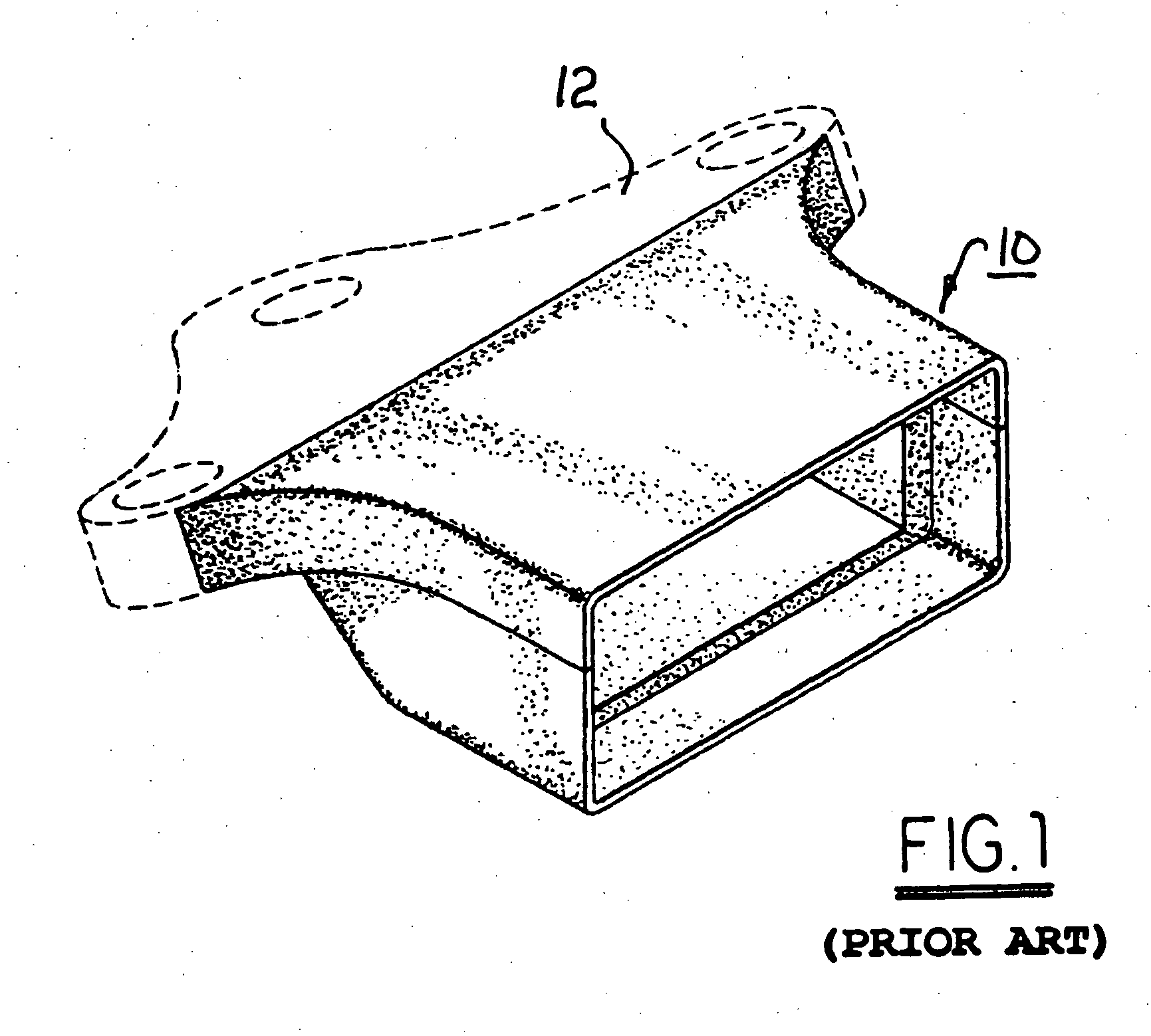
[0027] Referring to FIG. 1, a prior art headlight housing 10 for mounting adjacent to a prior art motorcycle triple tree 12 is shown, substantially as disclosed in U.S. Pat. No. Des. 374,730, issued Oct. 15, 1996 to Hauser. Housing 10 clearly demonstrates the benefit of a headlight mounting that is positioned by a triple tree crossmember, but housing 10 still presents a bulky and protrusive form for carrying a headlight well ahead of and sdeparate from the triple tree. Further, this design patent is silent as to the type and number of lamps for which the housing is suitable. Housing 10 does not suggest the benefit of forming the triple tree crossmember itself as a housing for one or more miniature high-intensity lamps and control circuitry, as is novelly described and claimed herein.

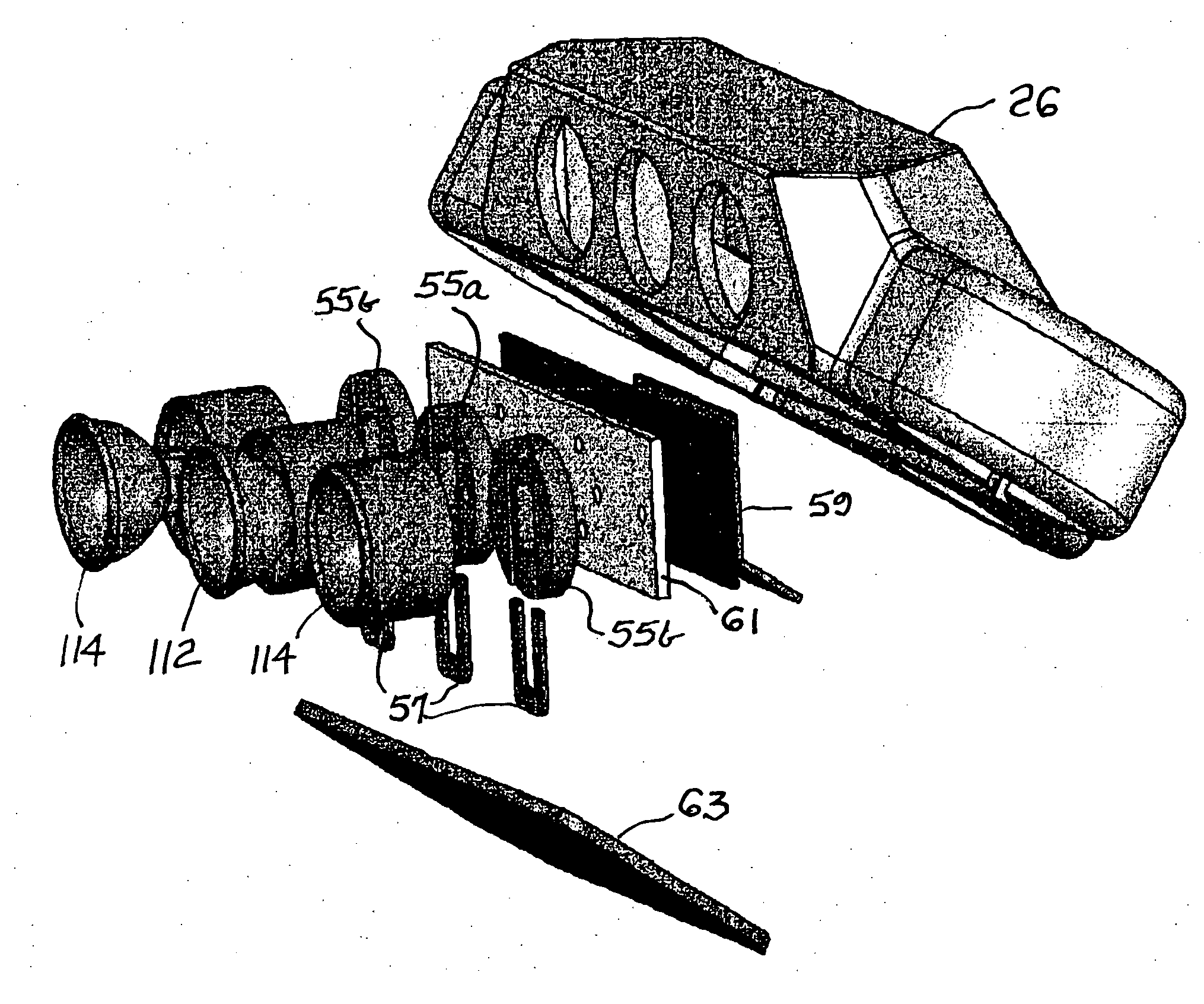
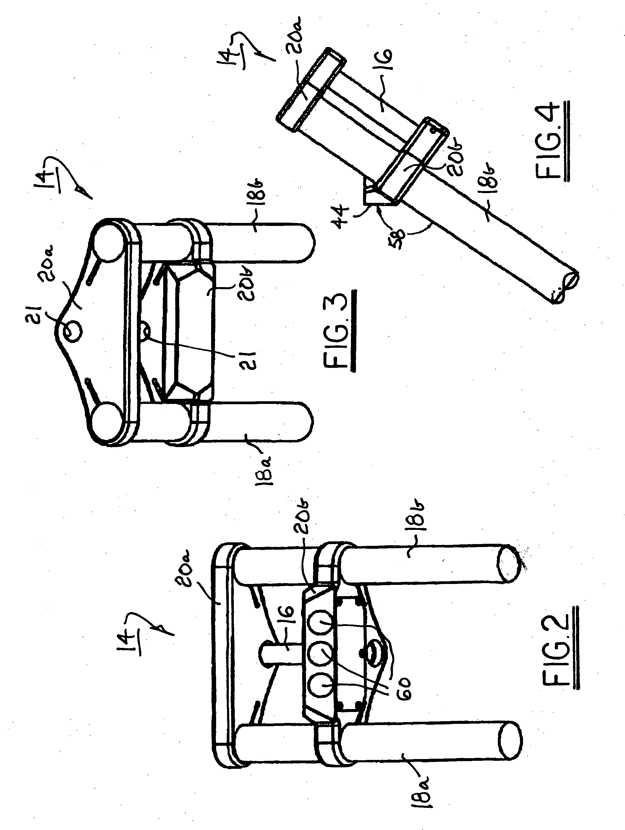
[0028] Referring to FIGS. 2 through 4, a steering head 14, in accordance with the invention, for a motorcycle (not shown) defines a pivot post 16 fixedly disposed on the motorcycle, right and left steer...


PUM


Abstract

A high intensity lamp system for a motorcycle incorporating a plurality of commercially available integral reflector halogen lamps within a crossmember element of a motorcycle triple tree assembly. A control system continually adjusts the power delivered to the lamps to maintain safe operating temperature to maximize bulb life at light intensity levels consistent with vehicular applications for headlighting applications. This is achieved using lamps not intended for sealed operation and the high shock and vibration environment of a vehicular or motorcycle application. A microprocessor-based digital control system of the preferred embodiment permits additional control and continual adjustment of lamp power to eliminate visible dimming of the lamps dependant on engine speed and state of the vehicle charging system, which dimming is evident in prior art use of high intensity lamps operating at light output levels reduced from maximum ratings for bulb life considerations.

Description

RELATIONSHIP TO OTHER APPLICATIONS AND PATENTS [0001] This Application draws priority from a pending U.S. Provisional Application Ser. No. 60 / 540,928, filed Jan. 30, 2004.TECHNICAL FIELD [0002] The present invention relates to motorcycles; more particularly, to headlight means for a motorcycle; and most particularly, to method and apparatus for mounting and operating commercially available high-intensity lamps within a motorcycle triple tree crossmember to provide headlight operation within safe operating limits and acceptable lamp life. BACKGROUND OF THE INVENTION [0003] It is known in the art of motorcycle headlight design to provide for a variety of streamline shapes for a motorcycle headlight housing and faring in conjunction with the so-called “triple tree” arrangement wherein a steering fork is pivotably mounted to a motorcycle frame, defining a steering head. See, for example, U.S. Pat. Nos. D374,730; D423,126; and D495,815S. Further, in some applications it is desired for st...

Claims


Application Information

Patent Timeline
IPC IPC(8): B62J6/02F21V33/00H05B39/04
CPCB62J6/02Y02B20/144H05B39/047B62J6/015B62J6/024Y02B20/00
Inventor HOOD, ROGER A.SOMERWILL, DAVID THOMAS
Owner NIAGARA PRECISION
Learn More