
Electrostatic discharge circuit and display panel

Active Publication Date: 2020-07-30
HKC CORP LTD +1
View PDF0 Cites 0 Cited by
  • Summary
  • Abstract
  • Description
  • Claims
  • Application Information

AI Technical Summary

Benefits of technology

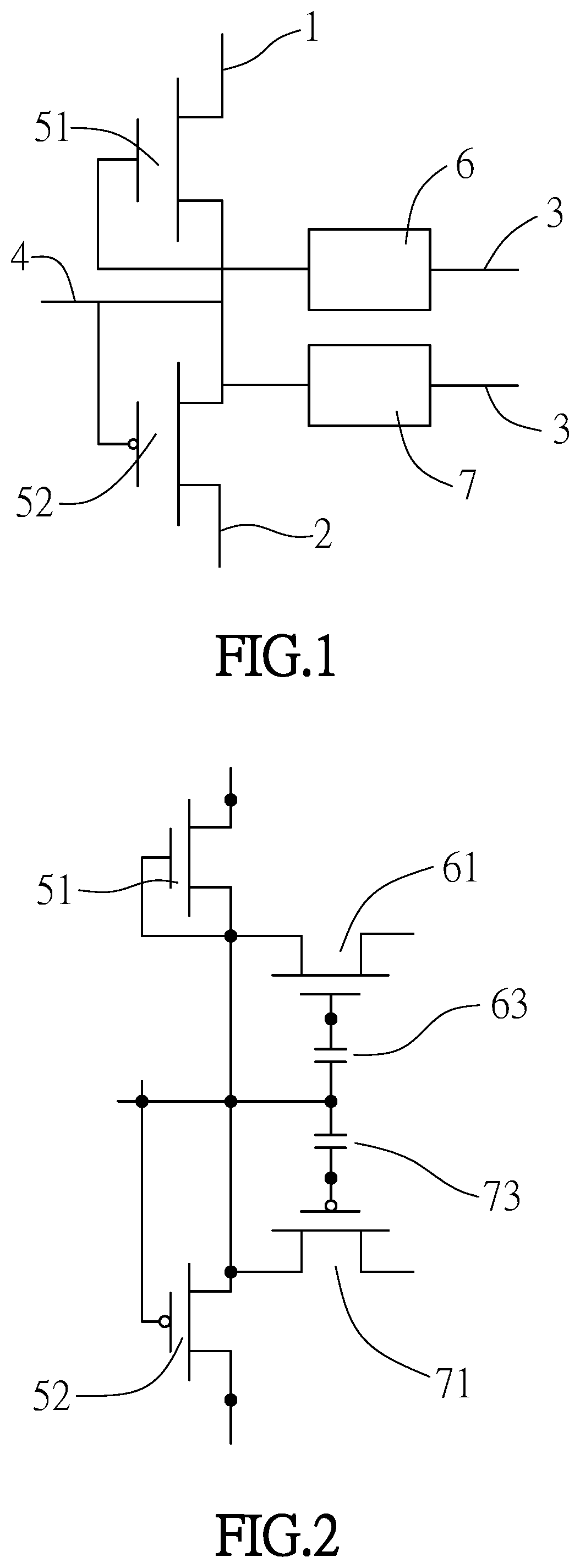
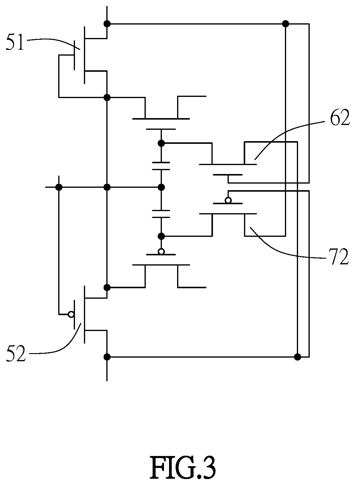
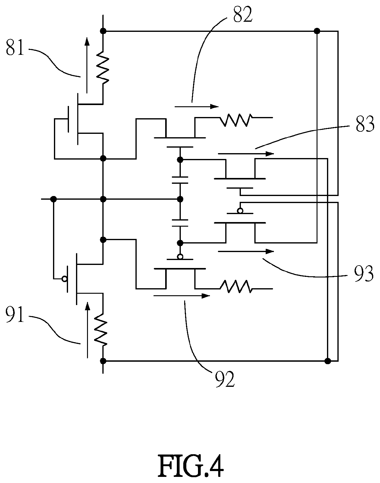
The patent text describes a display panel with three discharge units: the first discharge unit, the second discharge unit, and the third discharge unit. These three units work together to increase the speed and amount of discharge, protect the display panel, and extend the lifetime of the panel. The second discharge unit includes a second electroconductive wire, which is connected to the common terminal and grounded or connected to a common voltage terminal of the display panel. The second electroconductive wire has a small line width, which results in a higher resistance and lower discharge current. However, the first electroconductive wire has a larger resistance and higher discharge ability, so it is connected to the ground or common voltage terminal. The third discharge unit includes a third transistor, which allows for faster discharge through the fourth transistor. Overall, the patent text describes a display panel with three discharge units that work together to improve discharge performance and protect the display.

Problems solved by technology

This is equivalent to a larger resistance, the discharge current is also relatively smaller, and the discharge ability provided by the first discharge unit alone may not be sufficient.

Method used


Image

  • Electrostatic discharge circuit and display panel
  • Electrostatic discharge circuit and display panel
  • Electrostatic discharge circuit and display panel

Examples


Embodiment Construction

[0027]Specific structural and functional details disclosed herein are merely representative and are for purposes of describing example embodiments of the present invention. However, the present invention may be embodied in many alternate forms, and should not be interpreted as being limited to the embodiments set forth herein.

[0028]In the description of the present invention, it is to be understood that the term “center”, “lateral”, “upper”, “lower”, “left”, “right”, “vertical”, “horizontal”, “top”, “bottom”, “inner”, “outer” and other indicated orientation or positional relationships are based on the location or position relationship shown in the drawings, and are for convenience of description of the present invention only and to simplify the description, and not indicate or imply that refers to devices or elements must have a specific orientation, the orientation of a particular configuration and operation, therefore, cannot be construed as limiting the present invention. In addi...


PUM


Abstract

An electrostatic discharge circuit and a display panel are provided. The electrostatic discharge circuit comprises a first discharge unit, a second discharge unit and a third discharge unit. The first discharge unit comprises a first transistor and a second transistor, and a source of the first transistor is connected to a high level terminal. The gate and drain of the first transistor and the gate and drain of the second transistor are connected to an electrostatic input terminal. A source of the second transistor is connected to a low level terminal. An input terminal of the second discharge unit is connected to the electrostatic input terminal, an output terminal of the second discharge unit is connected to a common terminal. An input terminal of the third discharge unit is connected to the electrostatic input terminal, an output terminal of the third discharge unit is connected to the common terminal.

Description

BACKGROUNDTechnical Field[0001]This disclosure relates to a technical field of a display, and more particularly to an electrostatic discharge circuit and a display panel.RELATED ART[0002]Liquid crystal display has many advantages including the thin body, the power saving property and the radiation-free property and is widely applied. The existing liquid crystal displays are mainly backlight liquid crystal display which comprises a liquid crystal panel and a backlight module. The work principle of the liquid crystal display is that the liquid crystal molecules are placed between two parallel glass substrates, and a drive voltage is applied to the two glass substrates to control the rotating directions of the liquid crystal molecules so as to refract the light from the backlight module to generate an image.[0003]TFT-LCD (Thin Film Transistor-Liquid Crystal Display) has gradually occupied the dominant position in the display field due to its low power consumption, excellent image quali...

Claims


Application Information

Patent Timeline
IPC IPC(8): G09G3/36
CPCG09G2310/0248G09G3/3677G09G3/3696G09G3/3688G09G3/3648G09G2330/06G02F1/133H02H9/04
Inventor CHEN, YU-JEN
Owner HKC CORP LTD
Learn More