Electrostatic atomizing device and air conditioner using same

Inactive Publication Date: 2011-06-02
PANASONIC CORP
View PDF28 Cites 0 Cited by
  • Summary
  • Abstract
  • Description
  • Claims
  • Application Information

AI Technical Summary

Benefits of technology

[0011]a control portion which reduces the electric field intensity of the electric field generated by the atomizing electrode when the discharge detection portion detects the occurrence of the negative ion discharge.
[0012]Negative ion discharge is unnecessary in applications to air conditioners for the purpose of deodorization. And, negative ion discharge imparts damage to the atomizing electrode. In t

Problems solved by technology

Further, a large quantity of charged fine water particles is dispersed into the air.
However, in such applications, there arises a problem which is not present in dryers.
This problem is that negative ion discharge, in the initial state with no water droplets which is effective in a dryer, has no effect for the above-de

Method used


Image

  • Electrostatic atomizing device and air conditioner using same
  • Electrostatic atomizing device and air conditioner using same
  • Electrostatic atomizing device and air conditioner using same

Examples


Example

[0026]First, electrostatic atomizing devices of first to seventh embodiments of the invention are explained, together with drawings. And finally, an air conditioner of an embodiment of the invention is explained, together with drawings.

Electrostatic Atomizing Devices

Example

Embodiment 1

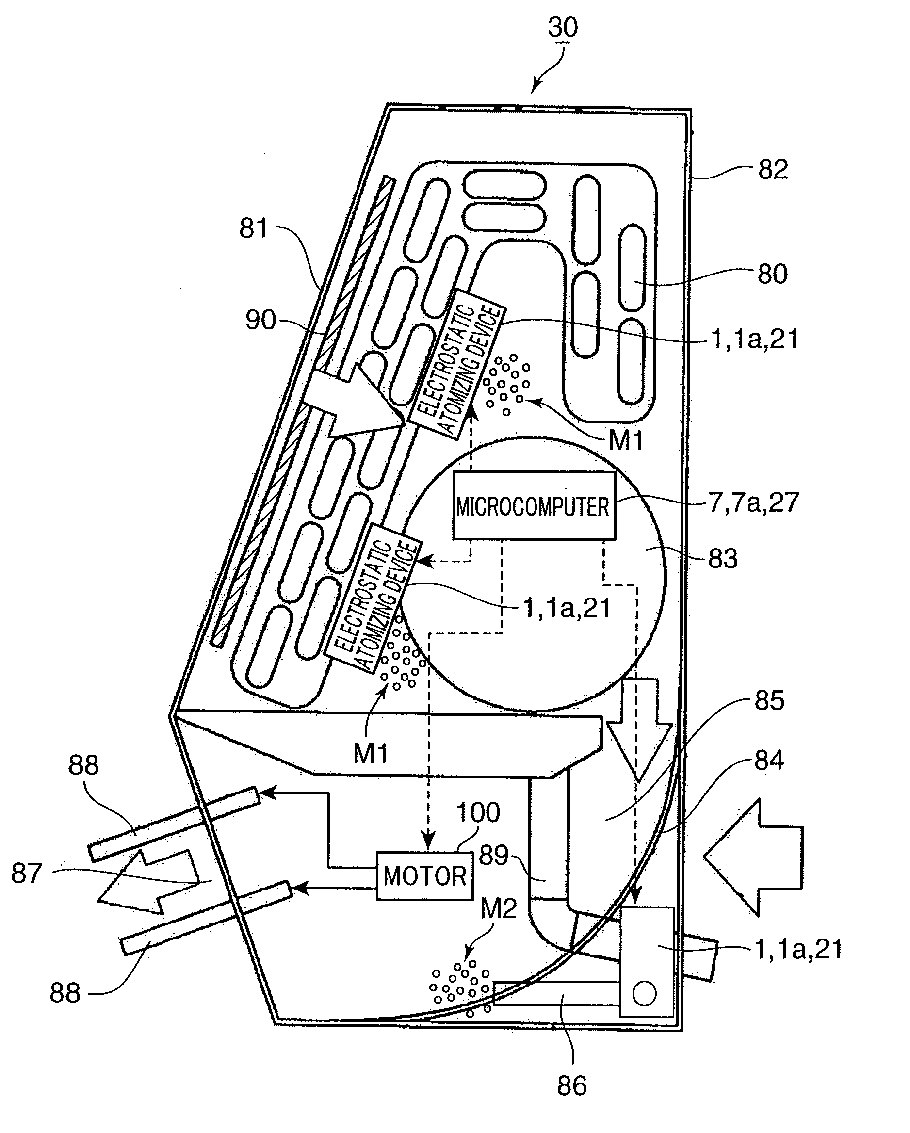
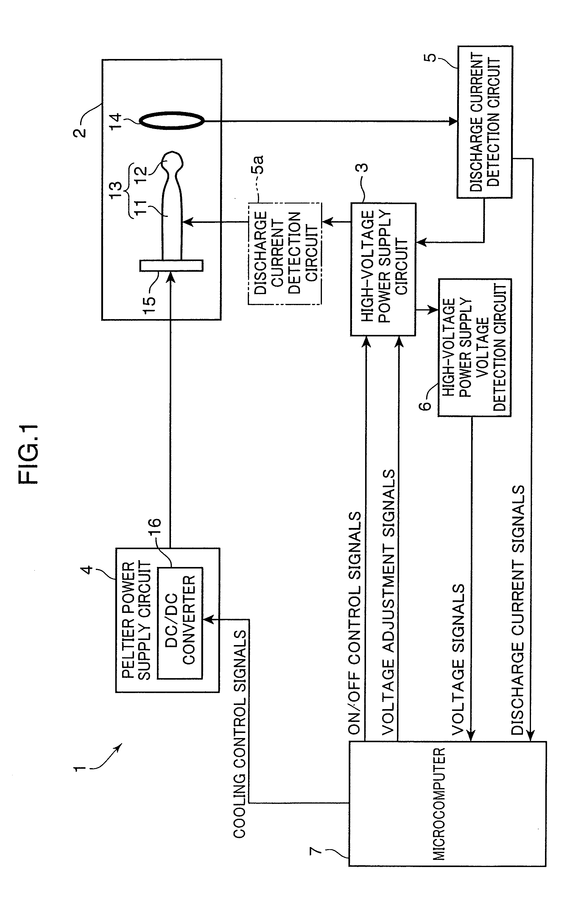
[0027]FIG. 1 is a block diagram showing the electrical configuration of the electrostatic atomizing device 1 in a first embodiment of the invention. This electrostatic atomizing device 1 comprises an atomizing block 2, high-voltage power supply circuit 3, Peltier power supply circuit 4, discharge current detection circuit 5, high-voltage power supply voltage detection circuit 6, and microcomputer (control portion) 7. This electrostatic atomizing device 1 is provided on the downstream side in the direction of flow of air from the filter 90 of an air conditioner 30 (see FIG. 13). For example, if the air conditioner is air cleaning equipment, charged fine water particles (nano-size mist) leaving the electrostatic atomizing device 1 by means of an ion wind generated from an ion generation portion (not shown) is carried on the air current of the air conditioner 30, and is dispersed within the room.

[0028]The atomizing block 2 comprises an atomizing electrode 13 having a spheri...

Example

Embodiment 2

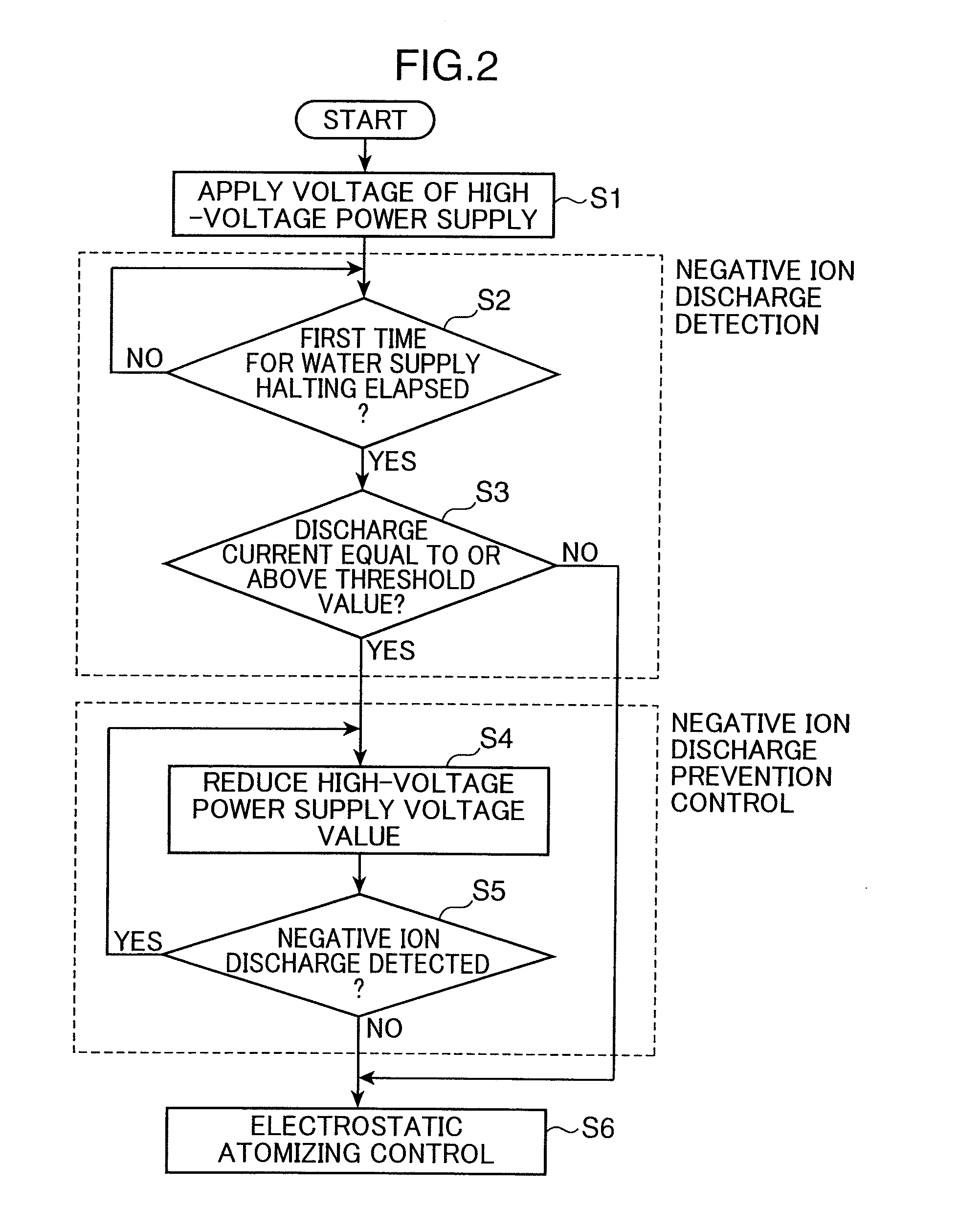
[0053]FIG. 5 is a flowchart used to explain operation of the electrostatic atomizing device 1 in a second embodiment of the invention. The configuration of the electrostatic atomizing device 1 shown in FIG. 1 can be used in the electrostatic atomizing device 1 of this embodiment. In the electrostatic atomizing device 1 of this embodiment, operation of the microcomputer 7 differs between in FIG. 2 and in FIG. 5. In FIG. 5, which is similar to FIG. 2, the same step numbers are assigned to corresponding processing, and explanations thereof are omitted. It should be noted that in this embodiment, after halting supply of water and waiting for a first time in step S2, upon detecting a discharge current value of the discharge current equal to or greater than a threshold value in step S3, no judgment of negative ion discharge is performed immediately, and processing returns to step S3 until a predetermined second time elapses, and after the second time has elapsed, judgment of n...


PUM


Abstract

An electrostatic atomizing device includes an atomizing electrode which generates charged fine water particles negatively charged in the form of mist, by generating an electric field when a high negative voltage is applied thereto in a state in which water is supplied; a water supply portion which supplies the water to the atomizing electrode; a discharge detection portion which detects whether negative ion discharge, indicating discharge in which only negative ions are generated without generating the charged fine water particles, is occurring at the atomizing electrode or not; and a control portion which reduces the electric field intensity of the electric field generated by the atomizing electrode when the discharge detection portion detects the occurrence of the negative ion discharge.

Description

TECHNICAL FIELD[0001]This invention relates to an electrostatic atomizing device, and to an air conditioner using such an electrostatic atomizing device.BACKGROUND ART[0002]An electrostatic atomizing device causes Rayleigh splitting of water supplied to an atomizer electrode to cause atomization by applying a high voltage across the atomizer electrode (discharge electrode) and an opposing electrode and inducing discharge. As a result, charged fine water particles of nanometer size (nano-size mist) are obtained. Such an electrostatic atomizing device is for example installed in a dryer, as in Patent Document 1 by the present applicant, and has been favorably evaluated. Various applications for such electrostatic atomizing devices are being studied. In particular, the charged fine water particles contain OH radicals, and have a long lifetime. Further, a large quantity of charged fine water particles is dispersed into the air. Hence charged fine water particles adhere can effectively a...

Claims


Application Information

Patent Timeline
IPC IPC(8): F25B21/02F23D11/32A61L9/14B05B5/025B05B5/057F24F1/00
CPCB05B5/006B05B5/0255B05B7/0075B05B5/0533B05B5/057B05B5/053
Inventor URATANI, YUTAKAOBATA, KENJIYANO, TAKESHIISAKA, ATSUSHI
Owner PANASONIC CORP
Why Eureka
Try Eureka