
Half-bridge-type control signal generating circuit and method thereof

a technology of control signal and generating circuit, which is applied in the direction of electric variable regulation, process and machine control, instruments, etc., can solve the problems of large energy loss, achieve the effects of improving the imbalanced phenomenon of signals, avoiding transformer burnout, and prolonging the life of lamps

Inactive Publication Date: 2006-02-07
NIKO SEMICON
View PDF7 Cites 14 Cited by
  • Summary
  • Abstract
  • Description
  • Claims
  • Application Information

AI Technical Summary

Benefits of technology

[0008]Accordingly, one object of the present invention is to provide a half-bridge-type control signal generating circuit and a method thereof, which can provide two control signals to control switching actions of two electronic switches of a half-bridge-type inverter circuit for converting DC power into AC power and providing an electric power for a load via a transformer.
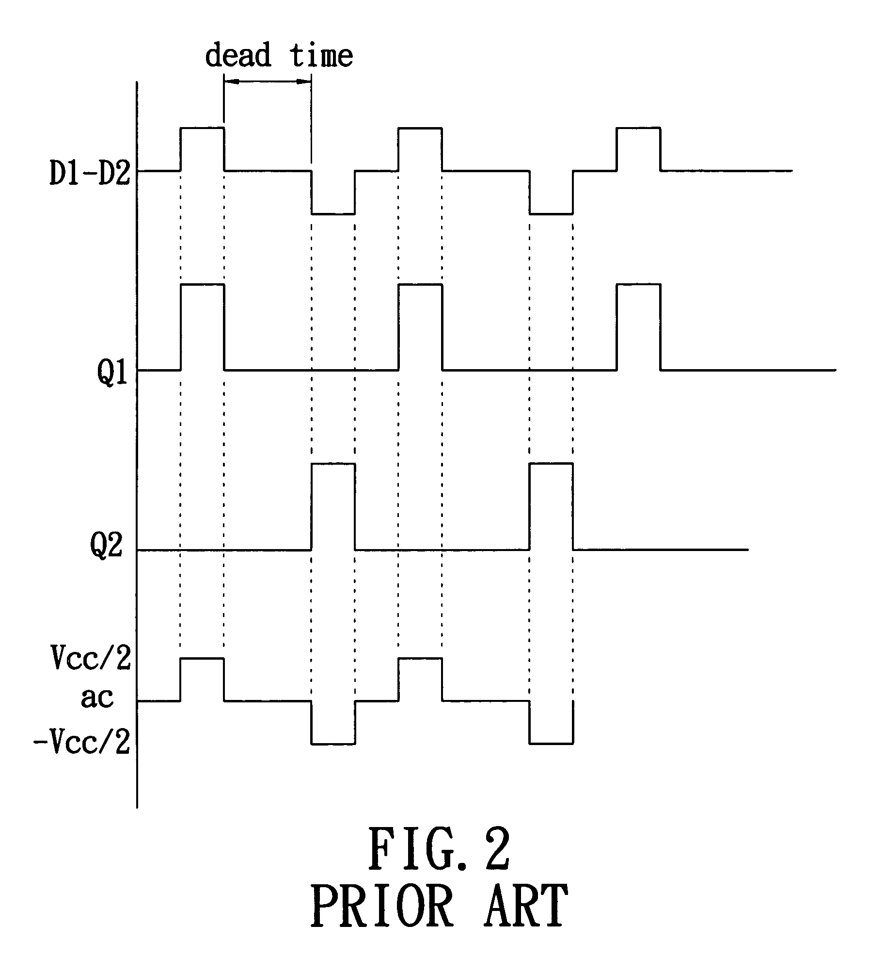
[0011]Furthermore, the present invention makes use of a dead time control unit to provide a constant dead time for avoiding burnout of the transformer due to the two electronic switches being simultaneously on. Moreover, the present invention can control and change the switching actions of the two electronic switches to provide the required electric power for the load based on the power requirement at the load end. Additionally, the present invention uses a soft boot unit to activate the two electronic switches for avoiding a too-large spike current or voltage when activating and lengthening the lifetime of the lamp.
[0012]The present invention can further use a sample and hold unit to receive a voltage feedback signal of the load end and perform a hold action of the voltage feedback signal at each clock signal for improving the imbalanced phenomenon of signals output to the load in the prior art.

Problems solved by technology

Because linear-type power source devices have more disadvantages, all power source devices manufactured now all of the switching-type.
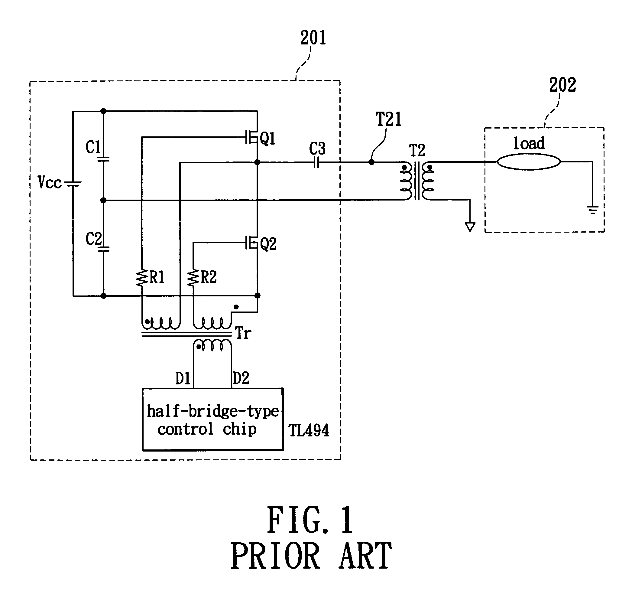
Moreover, both the electronic switches Q1 and Q2 used in the conventional half-bridge-type inverter circuit are n-channel FETs or p-channel FETs to cause larger energy loss.

Method used


Image

  • Half-bridge-type control signal generating circuit and method thereof
  • Half-bridge-type control signal generating circuit and method thereof
  • Half-bridge-type control signal generating circuit and method thereof

Examples


Embodiment Construction

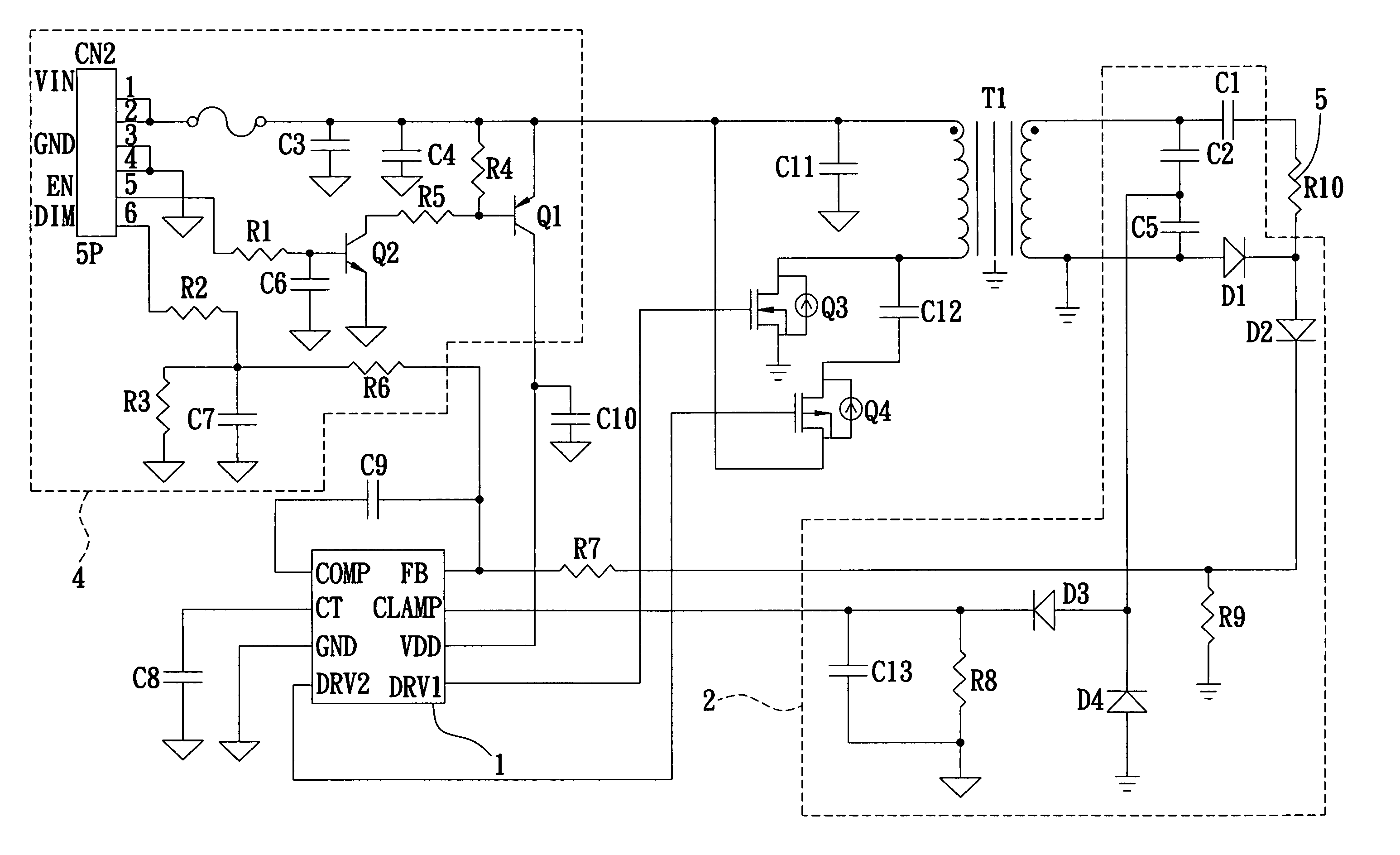
[0019]As shown in FIG. 3, a half-bridge-type control signal generating circuit 1 of the present invention is connected to a primary side of a transformer T1 via two electronic switches Q3 and Q4 for controlling the on / off states of the two electronic switches Q3 and Q4. The half-bridge-type control signal generating circuit 1 is also connected to a secondary side of the transformer T1 via a feedback circuit 2 to obtain a feedback signal of a load 5. The half-bridge-type control signal generating circuit 1 is also connected to a power supply unit 4 for providing a working power source Vdd (not shown). The half-bridge-type control signal generating circuit 1 outputs two control signals via a first output terminal DRV1 and a second output terminal DRV2 to control the on / off states of the two electronic switches Q3 and Q4 to convert a DC power source from the power supply unit 4 into an AC power source provided for the load. The above load is a cold cathode fluorescent lamp (CCFL). The ...


PUM


Abstract

A half-bridge-type control signal generating circuit outputs two control signals to control directly and drive switching actions of two electronic switches of a half-bridge-type circuit architecture. The half-bridge-type control signal generating circuit comprises an AND-gate logic unit, a NAND-gate logic unit, a circuit protection unit, a function generator, a clock generator, a soft boot unit connected to the clock generator, a sample and hold unit, a first comparator connected to the soft boot unit and the function generator, an OR-gate logic unit connected to the soft boot unit, the first comparator, the AND-gate logic unit and the NAND-gate logic unit, a second comparator connected to the sample and hold unit, the function generator, the AND-gate logic unit and the NAND-gate logic unit, and a dead time control unit connected to the function generator, the AND-gate logic unit and the NAND-gate logic unit.

Description

FIELD OF THE INVENTION[0001]The present invention relates to a half-bridge-type control signal generating circuit and a method thereof and, more particularly, to a signal generating circuit and a method thereof, which can output control signals and directly control and drive switching actions of a half-bridge circuit architecture to accomplish power conversion and transmission.BACKGROUND OF THE INVENTION[0002]For increasingly complex electronic and computer devices, power source devices become increasingly important. Power source devices can be divided into two categories: linear type and switching type. Because linear-type power source devices have more disadvantages, all power source devices manufactured now all of the switching-type.[0003]The power supply for a backlight source of a TFT LCD panel makes use of an inverter circuit to convert DC power into AC power for energy conversion and driving of a cold cathode fluorescent lamp (CCFL). Conventional inverter circuits can be divi...

Claims


Application Information

Patent Timeline
Patent Type & Authority Patents(United States)
IPC IPC(8): H02M3/335H02H7/122
CPCH02M1/08H02M3/33569H02M1/38H02M3/33571
Inventor WANG, YAO-CHEN
Owner NIKO SEMICON
Learn More