Fuel injection device

a fuel injection device and fuel injection technology, applied in the direction of lighting and heating apparatus, combustion process, climate sustainability, etc., can solve the problems of insufficient combustion efficiency at low power settings, excessive fuel in this region, easy smoke, etc., to achieve effective prevention of interference between pilot combustion region and main air flow, improve combustion efficiency, and enhance flame stability

Active Publication Date: 2018-11-20
KAWASAKI HEAVY IND LTD +1
View PDF77 Cites 10 Cited by
  • Summary
  • Abstract
  • Description
  • Claims
  • Application Information

AI Technical Summary

Benefits of technology

[0010]In order to solve the above-described problems, an object of the present invention is to provide a fuel injection device which achieves high combustion efficiency both at low power settings and at intermediate power settings while suppressing occurrence of smoke caused due to excess of a fuel.
[0012]With this configuration, by the flame stabilization plate including the inclined portion, interference between a pilot combustion region and main air flow is effectively prevented, thus the flame stability is enhanced, and the combustion efficiency is improved. In addition, the air supplied from the second opening flows into the inflow space between the flame stabilization plate and the partition wall plate to cool the flame stabilization plate. Thus, burnout of the flame stabilization plate is prevented. Furthermore, by the air being supplied from the first opening into the combustion chamber, it is possible to avoid a state where the fuel is excessive in the pilot combustion region, and thus it is possible to suppress occurrence of smoke.
[0013]In one embodiment of the present invention, the flame stabilization plate may include a peripheral wall portion which is continued to an upstream side of the inclined portion and extends in an axial direction, so as to form an outer periphery of the first opening. With this configuration, the air supplied from the second opening does not flow into the inner diameter side and is assuredly discharged in the radially outward oblique and downstream direction, and thus it is possible to further assuredly improve the combustion efficiency and suppress smoke.
[0015]In one embodiment of the present invention, the pilot fuel injector may be provided with a swirler configured to swirl the compressed air about an axis thereof. With this configuration, the fuel injected from the pilot fuel injector is diffused to the radially outer side by the swirler. Thus, the flame stability at the flame stabilization plate is ensured, and the combustion efficiency is further assuredly improved.

Problems solved by technology

However, in the device of Patent Document 1, an interference region remains between the pilot combustion region and the main combustion region, and thus the combustion efficiency at low power settings is insufficient.
Furthermore, when the fuel is intensively injected to the reverse-flow region on the axis as disclosed in JP Patent Application No. 2011-125481, the fuel is excessive in this region and smoke easily occurs.

Method used


Image

  • Fuel injection device
  • Fuel injection device
  • Fuel injection device

Examples


Embodiment Construction

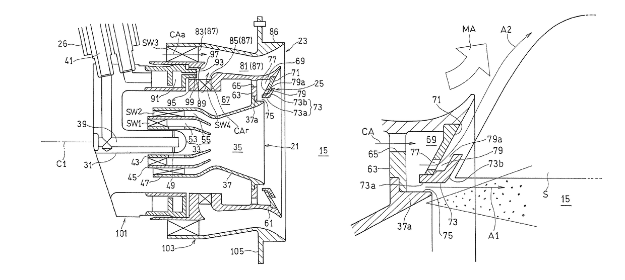
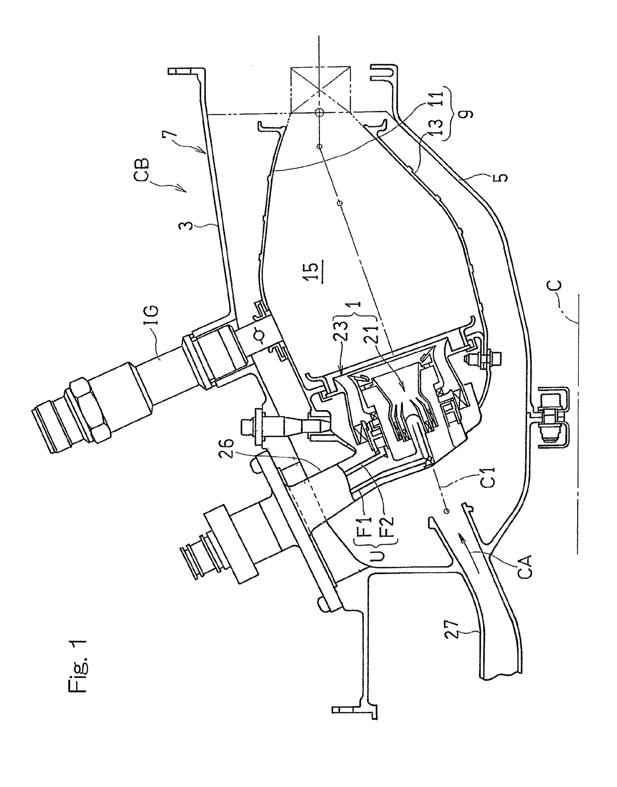
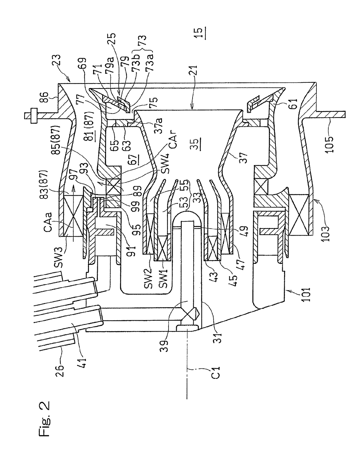
[0022]Hereinafter, embodiments of the present invention will be described in detail with reference to the accompanying drawings. FIG. 1 illustrates a combustor CB for a gas turbine engine equipped with a fuel injection device 1 designed in accordance with an embodiment of the present invention. The combustor CB is operable to mix fuel with a compressed air CA, fed from a compressor (not shown) of the gas turbine engine, and burn the resultant air-fuel mixture to produce high temperature and high pressure combustion gases, which are in turn fed to a turbine to drive this turbine.

[0023]The combustor CB is of an annular configuration and includes an annular outer casing 3 and an inner casing 5 located radially inner side of the outer casing 3, which casings 3 and 4 are positioned in a coaxial relation with an engine rotary longitudinal axis C so as to form a combustor housing 7 having an annular inner space defined therein. The annular inner space of the combustor housing 7 accommodate...


PUM


Abstract

A fuel injection device for supplying a fuel to a compressed air includes: a pilot fuel injector; a main fuel injector located at an outer periphery of the pilot fuel injector; and an air injection unit located between an outlet end portion of the pilot fuel injector and the main fuel injector. The air injection unit includes: a partition wall plate separating the air injection unit from a combustion chamber; a flame stabilization plate provided at a downstream side of the partition wall plate; a first opening at a downstream side between the flame stabilization plate and the outlet end portion of the pilot fuel injector; and a second opening provided in the partition wall plate and through which the compressed air is supplied. The flame stabilization plate includes an inclined portion inclined in a radially outward and downstream direction with respect to an axis.

Description

CROSS REFERENCE TO THE RELATED APPLICATION[0001]This application is a continuation application, under 35 U.S.C. § 111(a), of international application No. PCT / JP2013 / 065432, filed Jun. 4, 2013, which claims priority to Japanese patent application No. 2012-129681, filed Jun. 7, 2012, the disclosure of which are incorporated by reference in their entirety into this application.BACKGROUND OF THE INVENTION[0002]Field of the Invention[0003]The present invention relates to a fuel injection device for use in, for example, a gas turbine engine and, more particularly, to the fuel injection device equipped with a complex fuel injection device comprised of a plurality of fuel nozzles.[0004]Description of Related Art[0005]In recent years, in consideration of the environment, there is a need for a reduction of emissions such as NOx (nitrogen oxide) emitted from gas turbine engines. A fuel injection device of the conventional aircraft gas turbine combustor is of a diffusive combustion type, and s...

Claims


Application Information

Patent Timeline
Patent Type & Authority Patents(United States)
IPC IPC(8): F23R3/14F23R3/28F23R3/16F23R3/18F23R3/34
CPCF23R3/16F23R3/14F23R3/18F23R3/34F23R3/343F23R3/28Y02T50/675Y02T50/60
Inventor MATSUYAMA, RYUSUKEKOBAYASHI, MASAYOSHIHORIKAWA, ATSUSHIFUJIWARA, HITOSHI
Owner KAWASAKI HEAVY IND LTD
Why Eureka
Try Eureka