Protective device for a controlling system of a sewage pump

Inactive Publication Date: 2008-09-11
KEENER ROBERT M
View PDF19 Cites 10 Cited by
  • Summary
  • Abstract
  • Description
  • Claims
  • Application Information

AI Technical Summary

Benefits of technology

[0006]A main objective of the present invention is to provide a protective device for a controlling system of a sewage pump, wh

Problems solved by technology

According to above description, the conventional s

Method used


Image

  • Protective device for a controlling system of a sewage pump
  • Protective device for a controlling system of a sewage pump
  • Protective device for a controlling system of a sewage pump

Examples


Embodiment Construction

[0014]A protective device for a controlling system of a sewage pump in accordance with the present invention has a protective unit to protect a start capacitor and to avoid the start capacitor from burnout when an overload is occurred by actuating power source or when a transient voltage is occurred by malfunction of a controlling circuit after actuating the sewage pump. Therefore, the start capacitor is certainly protected and significantly improved in lifespan. The characteristic of this invention is that the protective device comprises an analogic or digital electronic circuit with a cutter function.

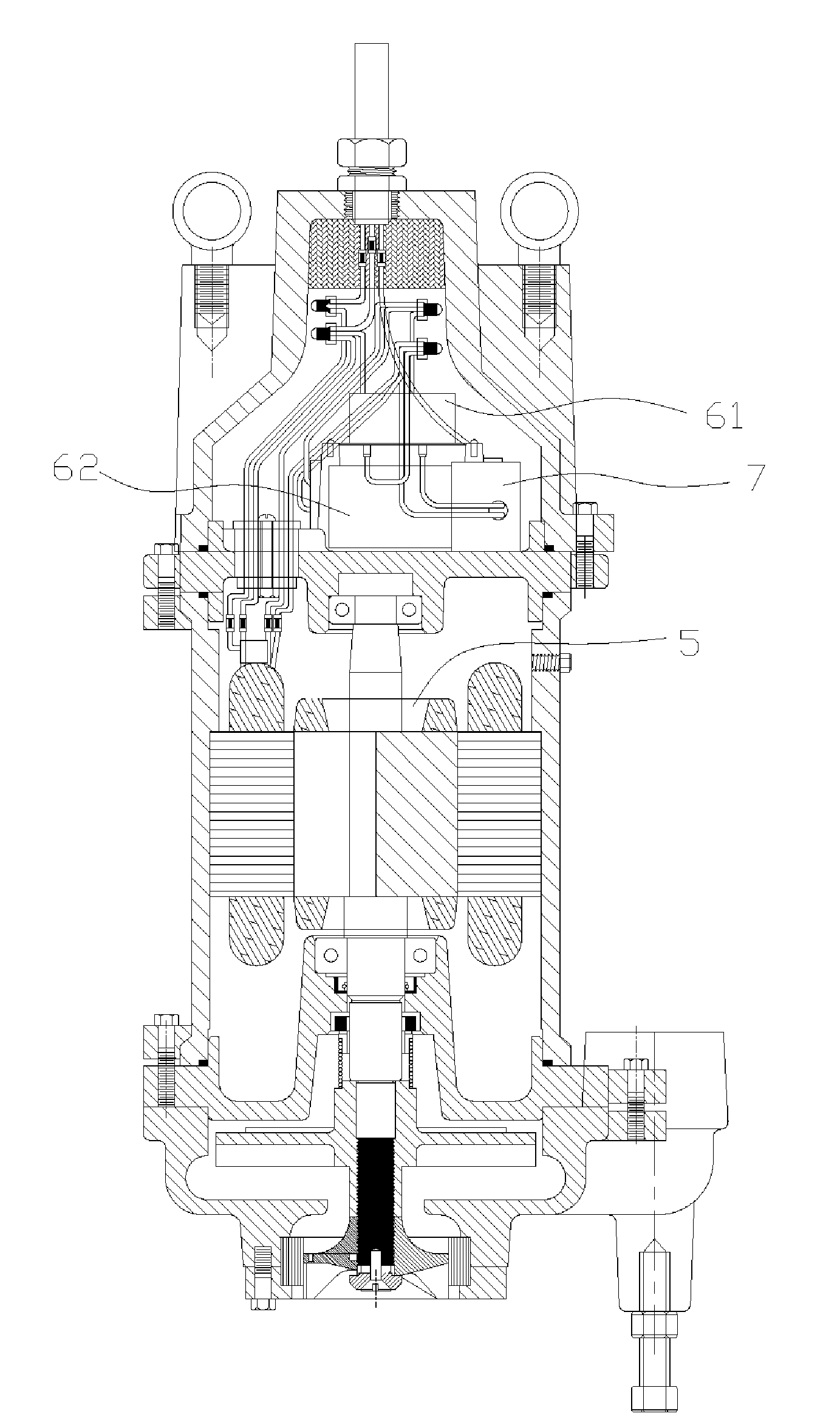
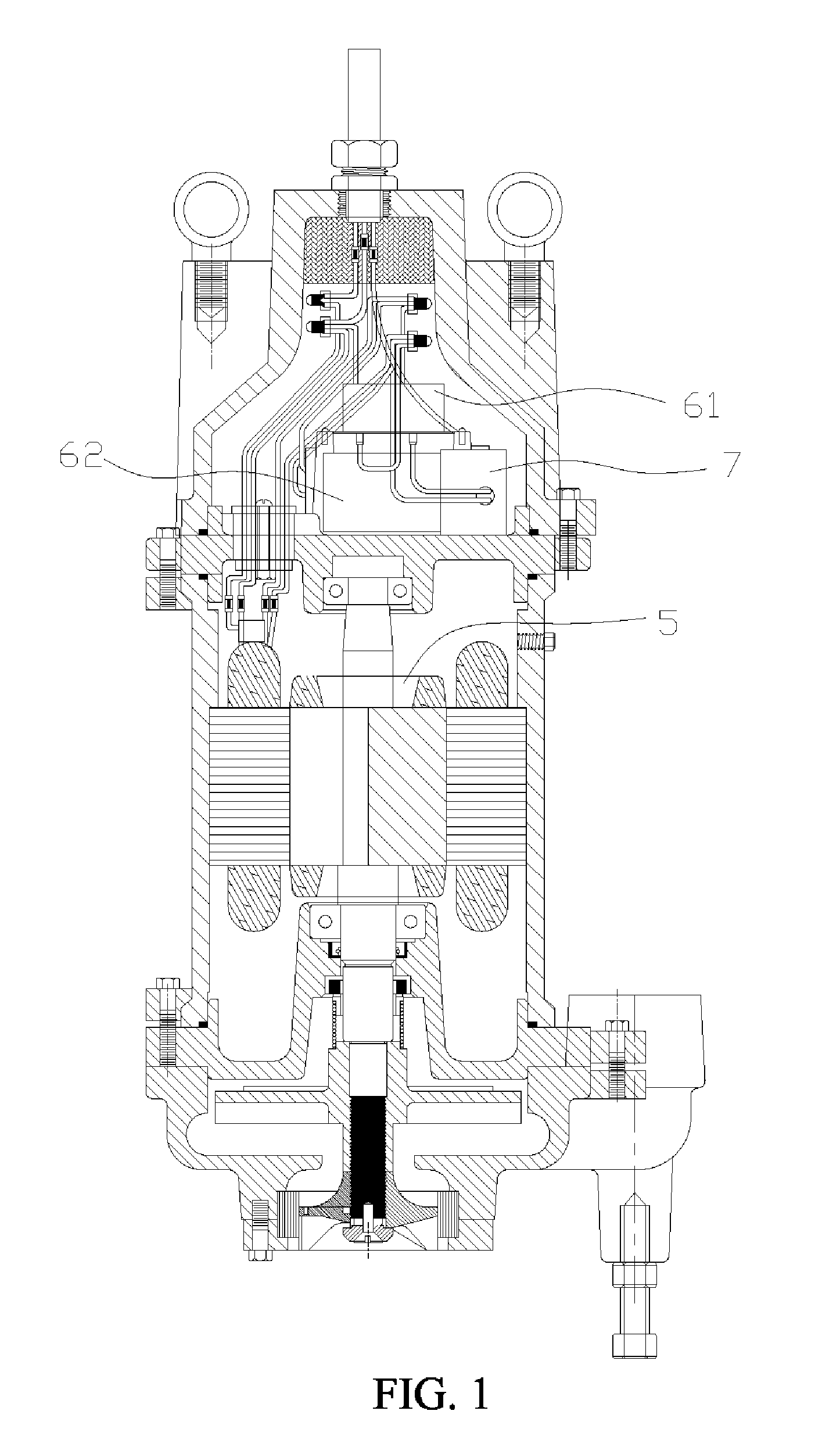
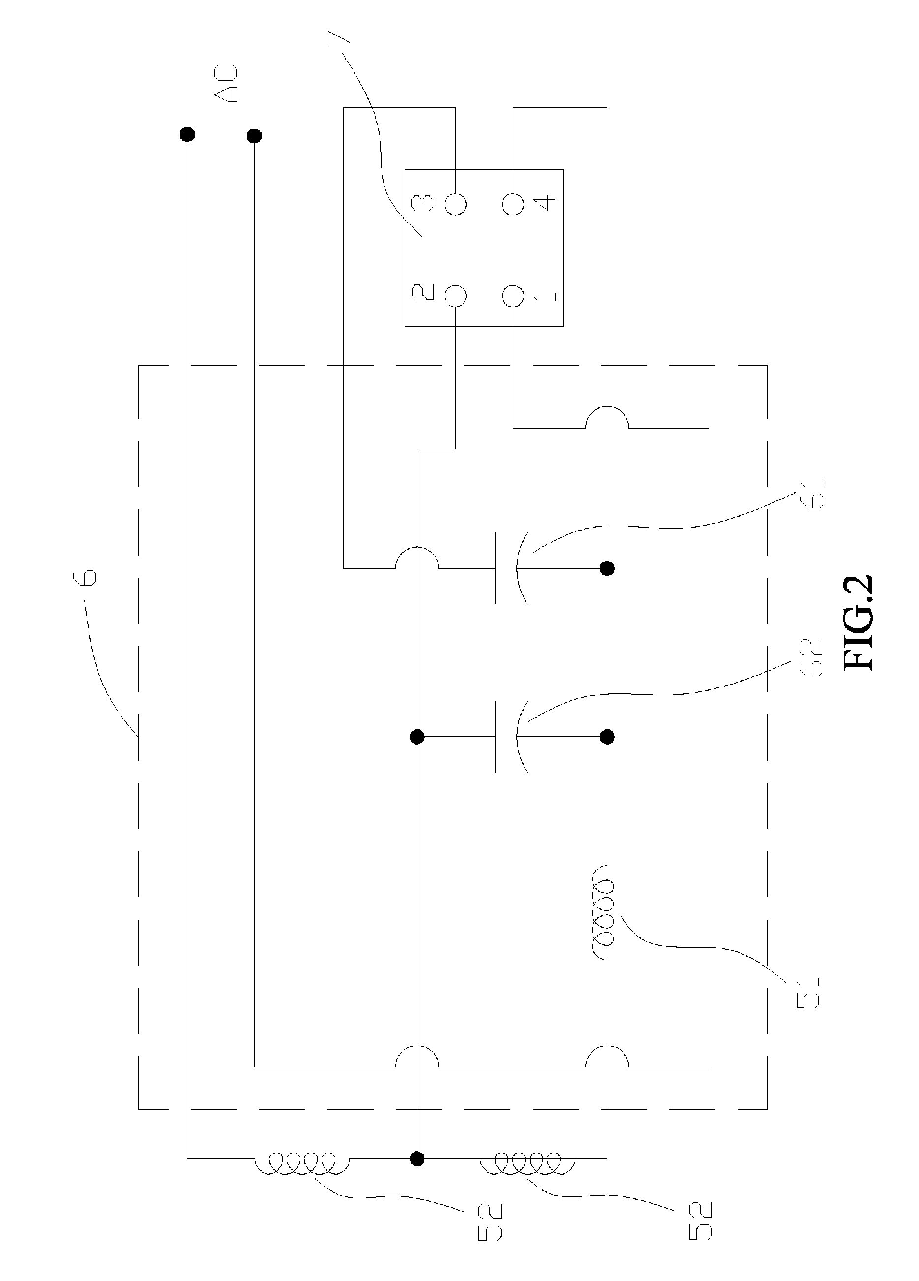
[0015]The protective device for a controlling system of a sewage pump is applied to an operation-controlling circuit system 6 to drive a sewage pump 5 as shown in FIG. 1, wherein the operation-controlling circuit system 6 as shown in FIG. 2 has a start capacitor 61 and a run capacitor 62. The start capacitor 61 has one end connecting to a first output terminal 3 on a protective unit 7...


PUM


Abstract

A protective device for a controlling system of a sewage pump has a protective unit to protect a start capacitor and to avoid the start capacitor from burnout when an overload is occurred by actuating power source or when a transient voltage is occurred by malfunction of a controlling circuit after actuating the sewage pump. Therefore, the start capacitor is certainly protected and significantly improved in lifespan. The characteristic of this invention is that the protective device comprises an analogic or digital electronic circuit with a cutter efficiency.

Description

BACKGROUND OF THE INVENTION[0001]1. Field of the Invention[0002]The present invention relates to a protective device for a controlling system of a sewage pump, and more particularly to an electronic-type protective device that controls pump operation and has a protective unit protecting a start capacitor in the controlling system to avoid the start capacitor from burnout.[0003]2. Description of Related Art[0004]As shown in FIGS. 3 and 4, a conventional sewage pump system in accordance with the prior art has an operational controlling circuit system 2 for controlling the operation of a sewage pump 1. The operational controlling circuit system 2 has a start capacitor 21 connected with a run capacitor 22 in parallel connection and with a switch 3 in series connection and further connected with an actuating coil and an operating coil on the sewage pump 1 to perform a combined circuit. In the operational controlling circuit system 2, the actuating coil 11 and the operating coil 12 drive ...

Claims


Application Information

Patent Timeline
IPC IPC(8): F04B49/00
CPCF04D13/083F04D13/086F04D15/0077
Inventor KEENER, ROBERT M.
Owner KEENER ROBERT M
Why Eureka
Try Eureka