Projector lamp control for increased lamp life

a projector and lamp control technology, applied in the field of projectors, can solve the problems of no electronic ballast technique known to change the fundamental life time of dc operated lamps, rapid burnback of hot anodes, and rapid degradation of dc lamp electrodes during lamp life, etc., to achieve the effect of prolonging the life tim

Inactive Publication Date: 2008-10-07
BARCO NV
View PDF21 Cites 13 Cited by
  • Summary
  • Abstract
  • Description
  • Claims
  • Application Information

AI Technical Summary

Benefits of technology

[0013]A consequence of this compensation is that lamp life of DC operated lamps can be extended. Otherwise the erosion of the anode surface in terms of pits and craters on the surface, accumulates gradually over time, which in turn causes the arc displacements to become gradually more pronounced in frequency and amplitude, causing more damage, and so on, until the light output drops or the flicker becomes unacceptable, and the lamp needs to be replaced. Hence the combination of DC drive and edge compensation by a fast feedback loop can reduce the rate of accumulation of damage, and lead to extended lamp life. It is an unexpected result of the method according to the present invention that by quasi instantaneously or instantaneously compensating for a leading edge of a detected change in lamp power output caused by each arc displacement, the lifetime is extended significantly.
[0021]In a second aspect, the present invention provides a projector system with improved life time, the projector system having a lamp control system according to embodiments of the present invention. Embodiments of the present invention can be applied to front and to rear projectors.
[0022]In a third aspect, the present invention provides a method of extending life time of a DC discharge lamp, especially a DC high intensity discharge lamp, the method comprising detecting and quasi instantaneously, preferably instantaneously, compensating for a leading edge of a lamp power output change caused by an arc displacement. “Quasi instantaneously” means that the compensation is carried out faster than the temporal response of the human visual system.
[0025]In a fifth aspect, the present invention provides the use of a lamp control system according to embodiments of the present invention to extend life time of a DC discharge lamp, in particular a DC HID lamp.

Problems solved by technology

Therefore, the hot anode quickly burns back.
Thus, while AC lamps can be regenerated for thousands of hours, DC lamp electrodes are degrading quickly during lamp life.
The above difficulties with DC lamps have resulted in specialised DC designs being developed which differ significantly from AC designs.
However, this requires symmetrical electrodes.
Although it is known to compensate for loss of electrode material, no electronic ballast technique is known to change the fundamental life time of DC operated lamps, especially ones with asymmetrical electrodes.
Furthermore, In addition, U.S. Pat. No. 4,373,146 states that electronic ballasts using DC lamp operation or phase control at low frequencies are not as desirable from a lamp life point of view.
However, as the flicker phenomena of DC HID lamps differs fundamentally from those of AC lamps, such methods have never been considered for DC lamps.

Method used


Image

  • Projector lamp control for increased lamp life
  • Projector lamp control for increased lamp life
  • Projector lamp control for increased lamp life

Examples


first embodiment

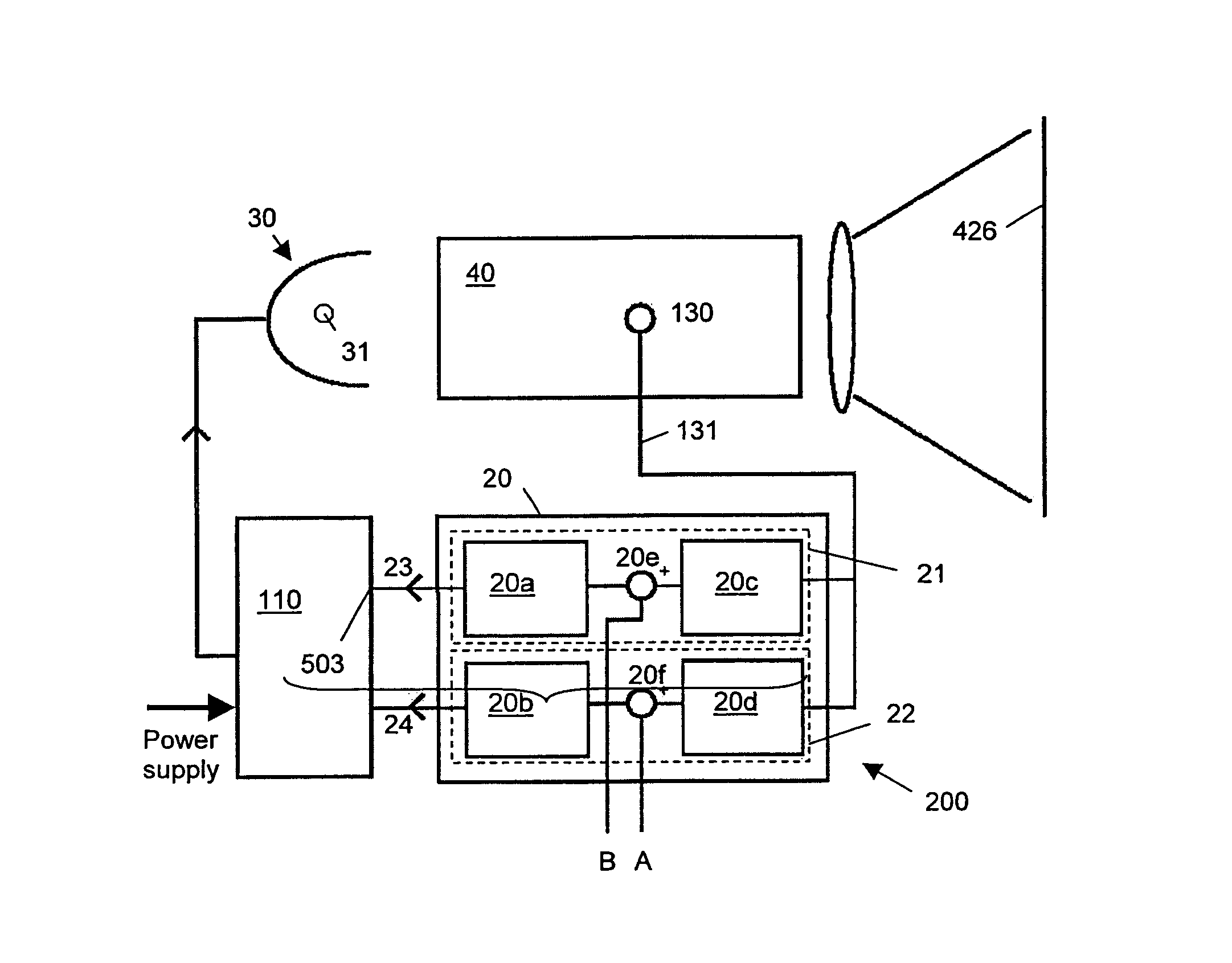
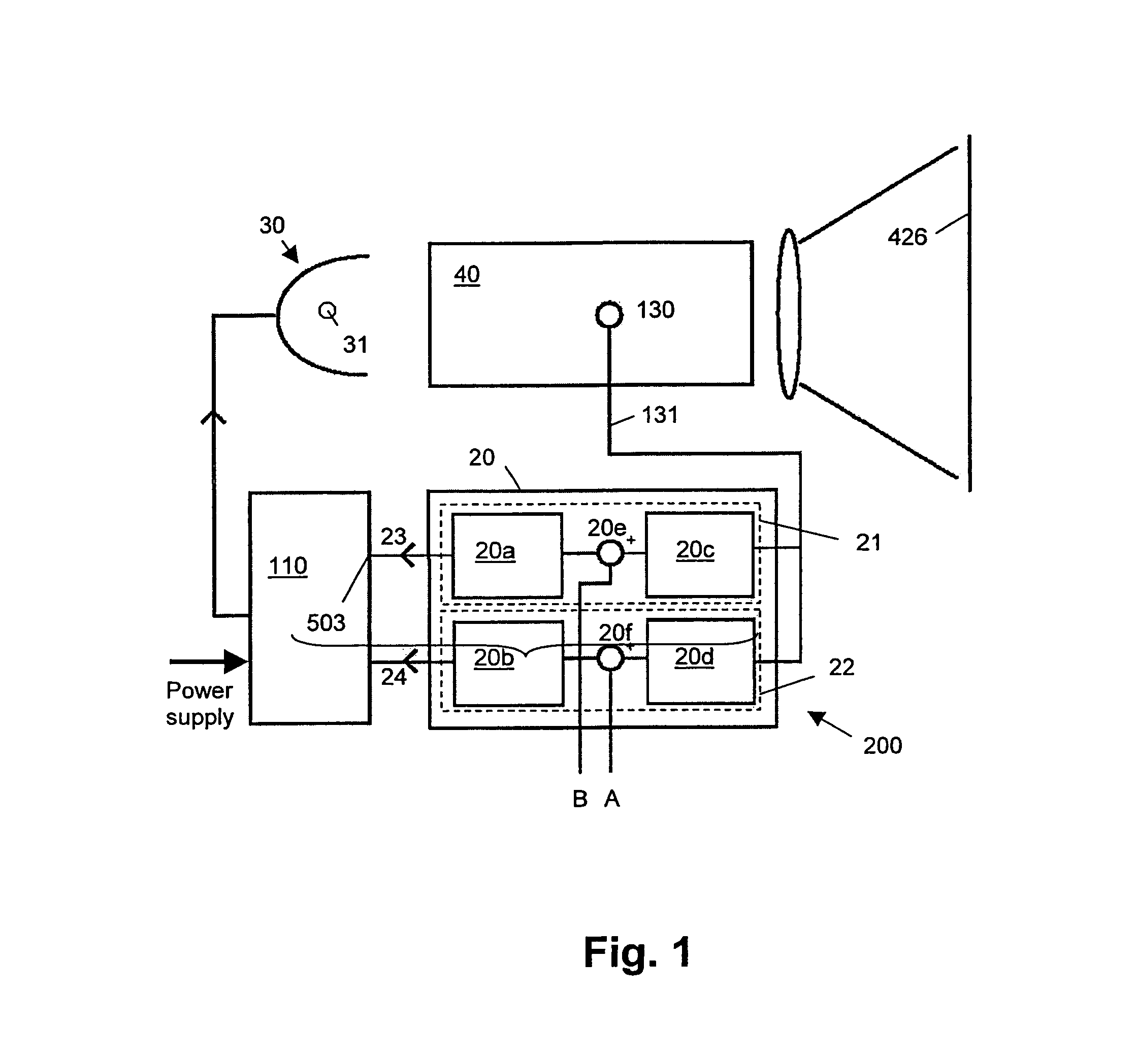
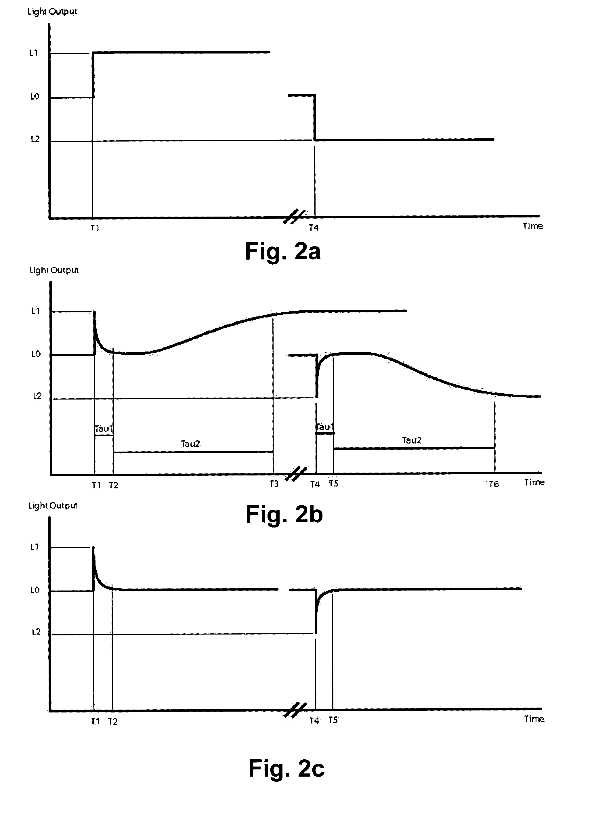
[0054]When the lamp-reflector assembly 30 and / or the illumination and modulation system 40 introduces a random disturbance, this will be detected by the light sensor 130, which generates a corresponding electrical signal 131. Through the high pass filter of the controller 20 this signal is returned to a processing means such as e.g. a differential amplifier, comparing this signal with a reference signal. The output of the controller 20 controls the lamp power supply 110 in order to achieve a constant light-flux on light sensor 130. The controlled light output in function of time, which is obtained with a system according to the present invention, is illustrated in FIG. 2b.

[0055]As can be appreciated from FIG. 1, according to an embodiment of the present invention, in fact two compensation loops may be provided in the lamp control system 200: a fast compensation loop and a slow compensation loop.

[0056]The fast compensation AC coupled loop is provided in the lamp control system 200, ...

second embodiment

[0081]According to the present invention, a multi-channel system is provided. An illustrative example of such multi-channel system is illustrated in FIG. 5. In a multi-channel system, a plurality of DC lamps are provided for illuminating different areas.

[0082]In a multi-channel projector system it is desirable to have all the projection devices in this system at the same output luminance level. This means the light-output of each projection device is equal if the illuminated area and the screen characteristics of all projection devices are identical. With a suitable communication system between the individual projection devices, the information of the light output levels can be exchanged between the projection device and adjusted to an equal luminance level.

[0083]FIG. 5 schematically shows an example of a multi-channel system with two channels A and B, however, this can be extended to any m×n configuration of illumination devices, e.g. projection devices such as rear and / or front pr...


PUM


Abstract

An electronic lamp control system for life time extension of a DC high intensity discharge lamp has a light sensor (130) for sensing an output of a lamp (31), a power supply (110) for the lamp (31), and a controller (20) for controlling the power supply (110). The controller (20) has a high pass filter (20c) for compensating for a leading edge of a detected change in lamp power output caused by each arc displacement. Lamp life is extended since damage to the lamp electrodes by the arc displacements is reduced. The system can have multiple lamps for the same illumination area, or multiple channels for illuminating different areas, coupled to provide uniform illumination. The controller (20) can compare a sensed level to a reference, to output a level control signal, then add a correction signal from the high pass filter to the level control signal.

Description

TECHNICAL FIELD OF THE INVENTION[0001]The present invention relates to lamp control systems, to projectors having such lamp control systems, and to corresponding methods.BACKGROUND OF THE INVENTION[0002]It is known to provide projection displays having high intensity discharge lamps. There are a number of major types of High Intensity Discharge (HID) lamp technologies, including for example ultra high pressure mercury, short arc xenon and short arc metal halide types. HID lamps typically have a quartz glass lamp bulb and tungsten electrodes. The quartz glass bulb is the discharge vessel containing the electrode system and is filled with a gas or gas mixture. To start an HID lamp an ignition voltage (a series of high-frequency pulses typically in the 30 kV range) is required. One electrode has the function of cathode; the other has the function of anode. When an electric field is passed between the electrodes, electrons are emitted from the cathode by thermionic emission; the anode h...

Claims


Application Information

Patent Timeline
Patent Type & Authority Patents(United States)
IPC IPC(8): H05B37/02
CPCH05B41/2928Y02B20/208Y02B20/00
Inventor CALLEWAERT, KURTCANDRY, PATRICKVERLEDENS, PAUL
Owner BARCO NV
Why Eureka
Try Eureka