Display apparatus

a display apparatus and optical modulation technology, applied in the field of passive optical modulation type display apparatuses, can solve the problems of reducing the life of the lamp, affecting the brightness of the display, and affecting the display effect, so as to prolong the lamp life and enhance the contrast ratio

Inactive Publication Date: 2008-10-21
MITSUBISHI ELECTRIC CORP
View PDF6 Cites 13 Cited by
  • Summary
  • Abstract
  • Description
  • Claims
  • Application Information

AI Technical Summary

Benefits of technology

[0010]The present invention is also directed to the display apparatus that comprises an image data input means that receives image data, a brightness extraction means that outputs the brightness data digitized based on the image data, the light source, a light source temperature controlling means that controls in response to the brightness data, light source temperature so that the temperature remains within the predetermined range. The display apparatus further comprises a light modulation device that displays images by receiving light emitted from the light source and by modulating the light in response to the image data, and a light source ignition means that adjusts the amount of light entering the light modulation means, by controlling in response to the brightness data, the electric power fed to the light source. A passive optical modulation type display apparatus that is designed to enhance its contrast ratio and to prolong its lamp lifetime can, therefore, be provided.

Problems solved by technology

The fact that the light modulation device in this display apparatus has inferior light modulation linearity and stray light enters the device, will worsen a contrast ratio of maximum to minimum brightness, so that the gray scale that the image data intrinsically retains are not allowed to be displayed.
As a result, a problem has been that when the wall temperature falls outside the proper temperature range, the halogen cycle will not work properly, thus resulting in a lamp lifetime being reduced.
Consequently, another problem has been that when the wall temperature lies outside the temperature range, the spectral distribution of the radiant light will vary, thus resulting in color characteristics, such as lamp color temperature and chromaticity, being changed.
Therefore, another problem has been that when the wall temperature goes out of the temperature range, the discharging impedance will vary, which causes a load on the electrode to change, resulting in the lamp lifetime being reduced.
Furthermore, when the lamp works properly so that the wall temperature remains within the temperature range, the amount of light emitted from the light source cannot be greatly changed.
Therefore, another problem has been that the contrast ratio cannot be greatly improved.

Method used


Image

  • Display apparatus
  • Display apparatus
  • Display apparatus

Examples


first embodiment

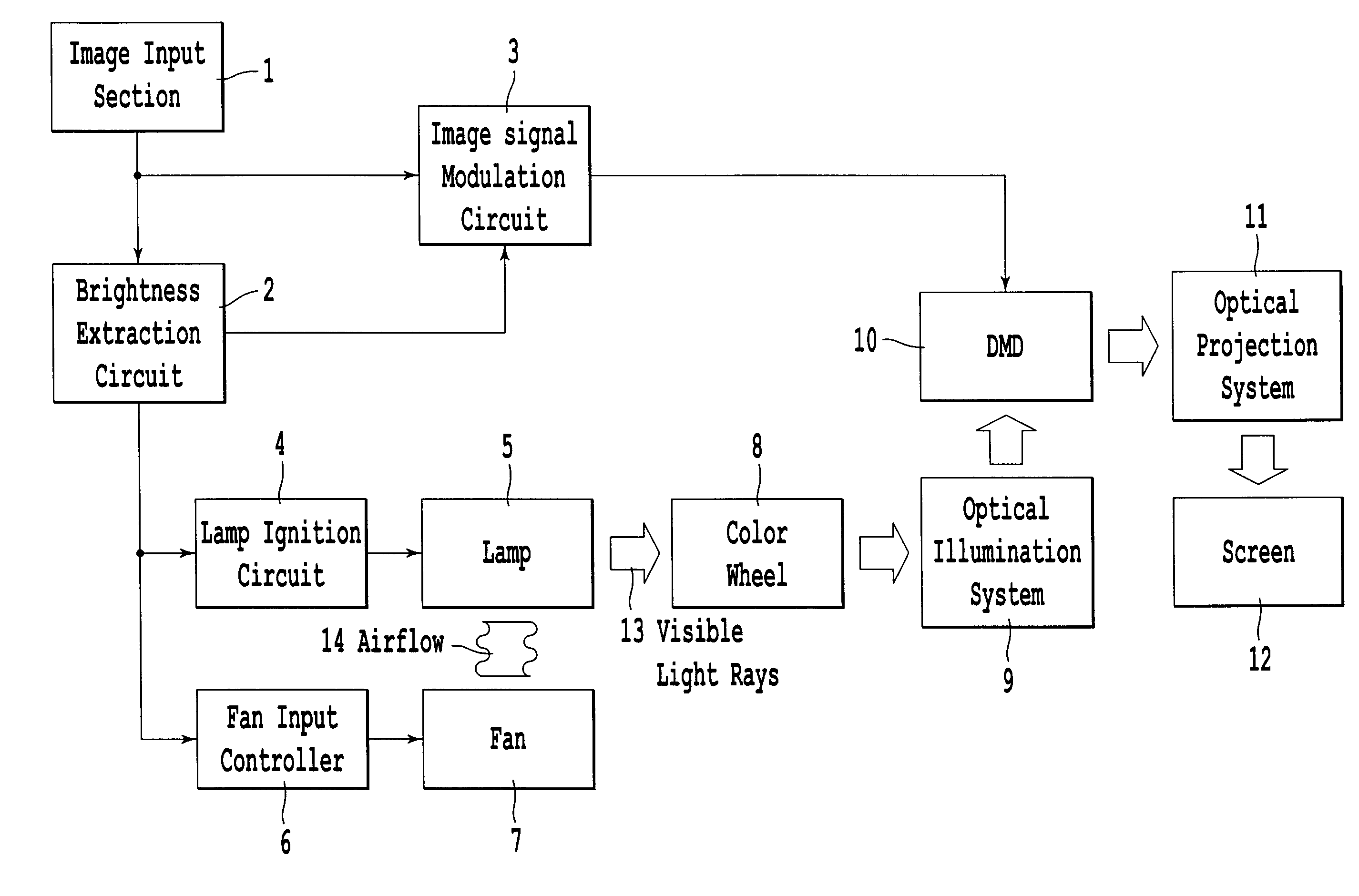
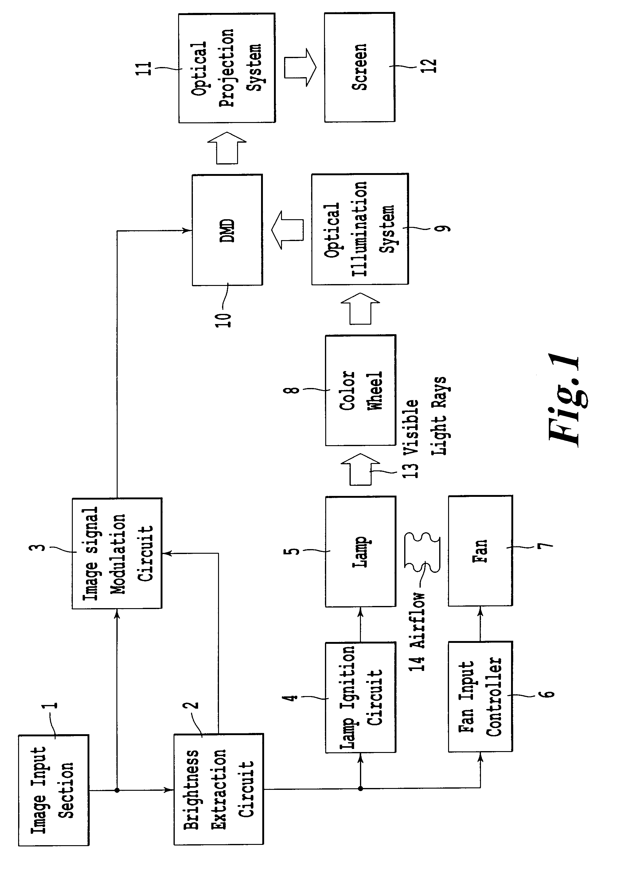
[0025]FIG. 1 is a system block diagram of a passive optical modulation type display apparatus in a first embodiment for implementing the present invention. In the embodiment, the passive optical modulation type display apparatus is a projection display that uses a DMD as a light modulation device. Referring to FIG. 1, the display apparatus includes as main unit a signal processing unit, a light source unit, a light source cooling unit, and an optical structure. Image data is inputted from an image input section 1—an image data input means.

[0026]The signal processor is constituted of a brightness extraction circuit 2 and an image signal modulation circuit 3. The brightness extraction circuit 2 digitizes according to the inputted image data (image signals) brightness features, to output them as brightness data. The brightness data digitized at the extraction circuit 2 may include average brightness, or peak brightness. Also, the brightness data may be digitized in accordance with brig...

second embodiment

[0040]FIG. 6 is a sectional side elevation of the lamp 5 and the wheel 8 in the present invention. Inclination of the wheel's rotational axis using the motor 15 can dynamically change within a range of zero through ten degrees the wheel's inclination with respect to the optical axis 26 of the lamp 5. Light rays emitted from the lamp 5 are reflected from the wheel 8 and returned to the bulb 21, which raises temperature of the bulb 21. This means that changing the wheel's inclination 28 to control the amount of light returning to the bulb 31 causes the temperature of the bulb 21 to be regulated. Namely, the motor 15 and the motor controller 16 control the inclination of the wheel 8 that reflects back to the lamp 5 the light rays emitted therefrom.

[0041]FIG. 7 is a graph illustrating a relationship between an inclination angle of the rotational axis of the wheel 8 with respect to the axis 26 corresponding to the lamp power and the bulb top temperature. The lamp 5 is the same as that in...

fifth embodiment

[0058]FIG. 12 is a graph illustrating a relationship between the amount of light entering the light modulation device and the lamp power, and a relationship between the amount of light and an aperture ratio of the iris aperture diaphragm, in the present invention. In order to achieve high contrast by extensively adjusting the amount of light, the diaphragm means such as the aperture diaphragm 46 is utilized. In order to increase the luminous efficiency of the display apparatus by reducing the lamp power, the amount of light emitted from the lamp 5 itself is adjusted. Consequently, combining those methods achieves a high contrast ratio and high luminous efficiency. Referring to FIG. 12, the horizontal axis of the graph shows a relative value of the amount of light entering the light modulation device; the left vertical axis, the lamp power; the right vertical axis, an aperture ratio of the aperture diaphragm 46. The solid line shows changes of the amount of light being dependent of t...


PUM

PropertyMeasurementUnit
poweraaaaaaaaaa
brightnessaaaaaaaaaa
temperatureaaaaaaaaaa

Abstract

A display apparatus having a control unit which controls the light source temperature so that the temperature remains within a predetermined temperature range, a light modulation device for displaying images by receiving light emitted from the light source, and modulating the light according to the image data, and a light source controlling unit which adjusts the amount of light that enters the light modulation device, by controlling electrical power fed to the light source, according to the brightness data. Even if a contrast ratio is improved by changing the amount of light of an HID lamp, a passive optical modulation type display apparatus can be provided without reducing the lifetime of the light source lamp.

Description

BACKGROUND OF THE INVENTION[0001]1. Field of the Invention[0002]The present invention relates to passive optical modulation type display apparatuses in which the amount of light emitted from the light source can be changed.[0003]2. Description of the Related Art[0004]A conventional passive optical modulation type display apparatus employs a light modulation device, to modulate in response to image data inputted from outside, light emitted from the light source and thereby display images. By adjusting light modulation device optical transmittance or its reflectance, the display apparatus of the passive optical modulation type displays gray scale of the image data. The fact that the light modulation device in this display apparatus has inferior light modulation linearity and stray light enters the device, will worsen a contrast ratio of maximum to minimum brightness, so that the gray scale that the image data intrinsically retains are not allowed to be displayed.[0005]For this reason,...

Claims


Application Information

Patent Timeline
Patent Type & Authority Patents(United States)
IPC IPC(8): G03B21/26G02F1/133G03B21/16G03B21/18G03B21/20
CPCH04N9/3155H04N9/3197H04N9/3114
Inventor HARADA, SHIGEKITAMIDA, TAICHIROIWATA, AKIHIKO
Owner MITSUBISHI ELECTRIC CORP
Why Eureka
Try Eureka