Printing unit for a rotary printing machine with cross slide

a printing unit and rotary printing technology, applied in printing presses, office printing, printing, etc., can solve the problem of short adjustment travels

Inactive Publication Date: 2003-01-07
MANROLANAD AG
View PDF13 Cites 32 Cited by
  • Summary
  • Abstract
  • Description
  • Claims
  • Application Information

AI Technical Summary

Benefits of technology

The forme cylinder (6) can be moved and positioned in the direction of the double arrow B by means of first slide (7), and can be moved and positioned in the axial direction indicated by double arrow A by means of second slide (8). This subassembly, designated as a cross slide (7+8), is also used for the mountings of the further printing-unit cylinders (3, 4, 5), the slides (7) of the respectively co-operating cylinders (6, 5; 5, 4; 4, 3) being arranged alternately on the guides (10, 11) located opposite one another. By virtue of the alternating arrangement, the slides (7) can have a longer construction, so that more favorable guidance conditions prevail (guide length to guide width) and forces can be introduced more effectively into the side wall. Since the cylinder mountings can nevertheless be positioned very close to one another, it is also possible to use cylinders with a very small diameter.
The moveability of the cylinders in the direction of the double arrow B allows format variability, and, by means of accurate positioning of the slide (8) in the direction of the double arrow A, the lateral register can be set. In the case of cylinders (3, 4, 5, 6) mounted on both sides, a cross-slide unit (7+8) is preferably arranged on the driving side and only an axially moveable radial bearing on a slide (7) is arranged on the other side. A cross-slide unit (7+8) may, of course, also be provided on both mounting sides of the cylinders. The drives of the various slides (7, 8) on the two mutually opposite bearing sides of the cylinders are activated in such a way that the bearing points move synchronously with one another.

Problems solved by technology

However, only very short adjustment travels are possible with these.

Method used


Image

  • Printing unit for a rotary printing machine with cross slide
  • Printing unit for a rotary printing machine with cross slide
  • Printing unit for a rotary printing machine with cross slide

Examples


Embodiment Construction

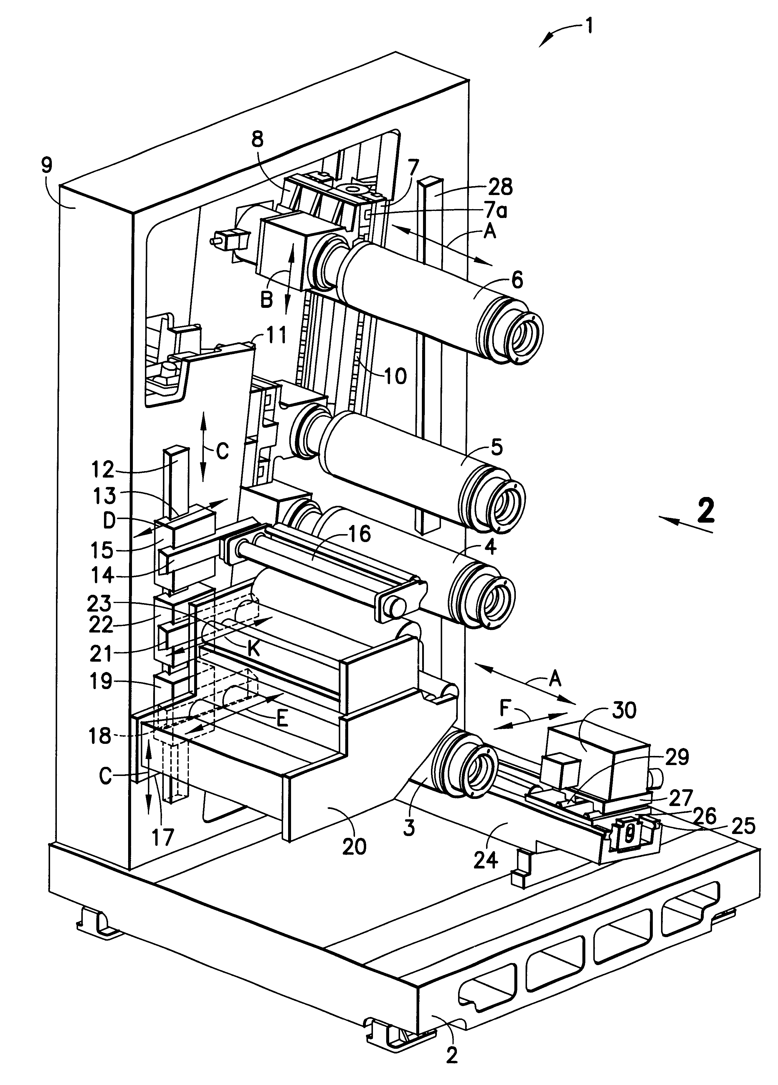
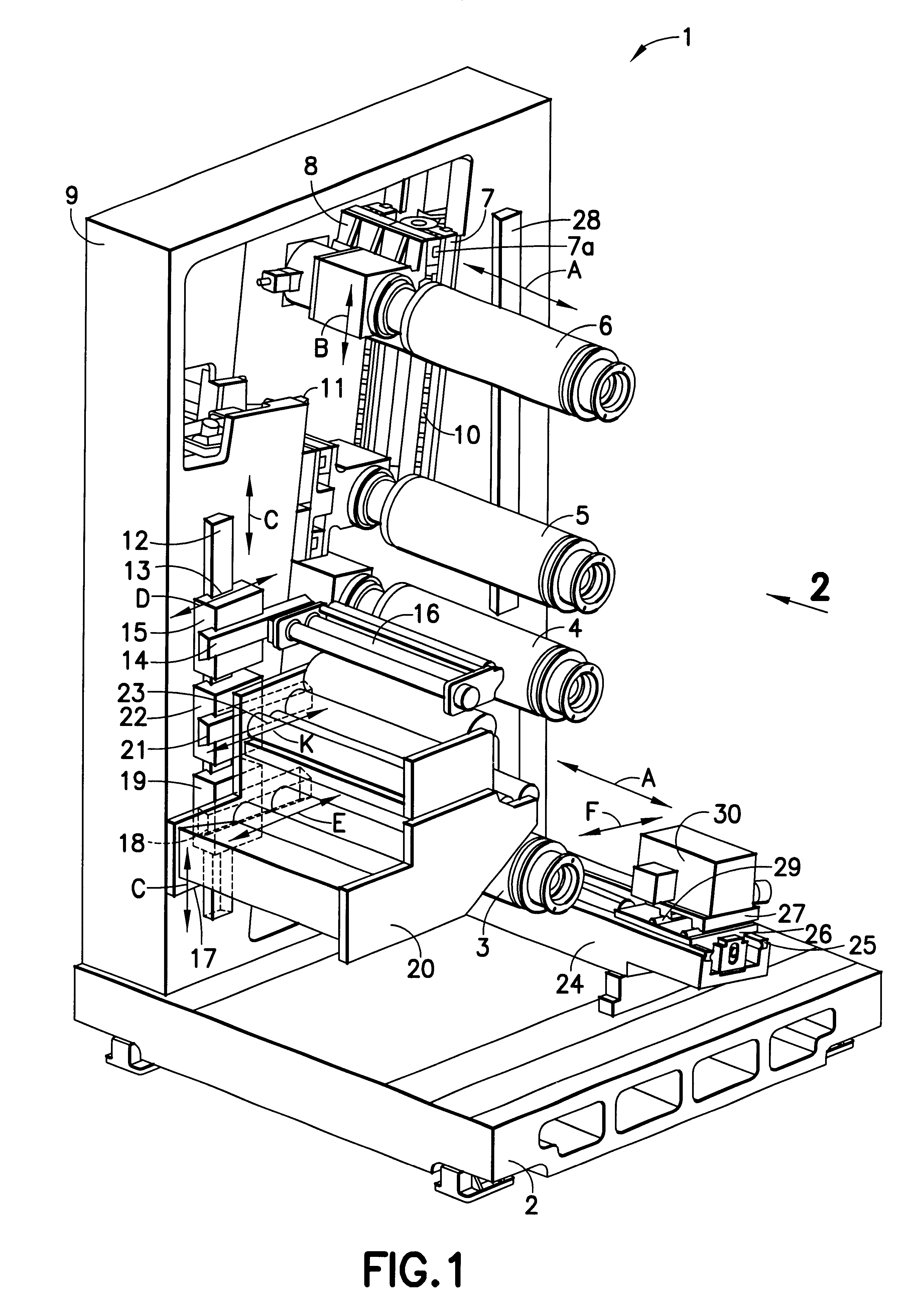
FIG. 1 illustrates a three-dimensional view of a printing unit (1). In order to display the equipment, according to the invention, of this exemplary embodiment, an illustration of the front side wall and of other subassemblies not relevant for this purpose has been dispensed with.

The printing unit stands on a base plate (2) on which side wall (9) is supported. In exemplary embodiments with an overhung cylinder mounting, a second side wall may be dispensed with, so that the operating side is freely accessible.

The side walls (9) each have an aperture, at the two lateral boundaries of which guides (10, 11) are mounted essentially opposite one another. In this exemplary embodiment, two parallel rails are arranged as the first guide 10, in which a first slide (7) is guided. Arranged on first slide (7) is a second guide (7a) which is rotated through ninety degrees in relation to the first guide (10) and carries a second slide (8). The mounting of the forme cylinder (6) is fastened on seco...


PUM


Abstract

Rotary printing machine with forme and impression cylinders for variable-format or variable-circumference printing and with service apparatus which are capable of being moved radially in relation to the printing-unit cylinders for throw-on or throw-off movements and in the axial direction of the cylinders or in the side-wall plane. The service apparatus and the printing-unit cylinders are arranged on cross slides which can each be moved in two directions relative to the printing-unit side wall.

Description

PRIORITY CLAIMThis applications claims the priority of German Application No. 100 08 215.7, filed Feb. 23, 2000.1. Field of the InventionThe invention relates to a printing unit of a rotary printing machine having at least one forme cylinder and at least one impression cylinder which can be moved relative to each other, as well as service apparatus which can be moved relative to the cylinders.2. Description of the Related ArtU.S. Pat. No. 6,085,650 discloses a printing unit for a rotary printing machine, in which the distance between the transfer cylinder and forme cylinder is adjustable. It is thereby possible to use cylinders with different diameters and to print with a variable circumference, that is to say a variable format. The adjustability of the printing-unit cylinders is made possible by slides which are guided linearly on carriers and on which the cylinders are mounted.Multi-ring bearings, which make it possible by means of eccentrics to execute movements for throwing on o...

Claims


Application Information

Patent Timeline
Patent Type & Authority Patents(United States)
IPC IPC(8): B41F13/30B41F13/24B41F13/34B41F13/12B41F13/20
CPCB41F13/34B41F13/30B41F13/14
Inventor GOTTLING, JOSEFHARTMANN, THOMASPETERSEN, GODBER
Owner MANROLANAD AG
Why Eureka
Try Eureka