Traction-impact device and force transmission unit having such a traction-impact device

a technology of traction-impact device and force transmission unit, which is applied in the direction of yielding coupling, buffer cars, railway coupling accessories, etc., can solve the problems of inability to produce simple use inability to easily remove energy input intended for deformation work, and inability to produce energy with very little structural space available. , to achieve the effect of high recycling potential and short installation spa

Active Publication Date: 2019-10-10
VOITH PATENT GMBH
View PDF0 Cites 4 Cited by
  • Summary
  • Abstract
  • Description
  • Claims
  • Application Information

AI Technical Summary

Benefits of technology

[0007]The present invention provides a traction-impact device which, in addition to force transmission during normal operation, in the event of a crash also enables the absorption of significant forces in a short installation space which is available. In the even...

Problems solved by technology

Such embodiments are configured in such a manner that the plastic deformation is also already intended to be taken into account in the design and is generally also not able to be readily removed following a crash.
The deformation capacity is also connected with the material properties and geometry and sizing of...

Method used


Image

  • Traction-impact device and force transmission unit having such a traction-impact device
  • Traction-impact device and force transmission unit having such a traction-impact device
  • Traction-impact device and force transmission unit having such a traction-impact device

Examples


first embodiment

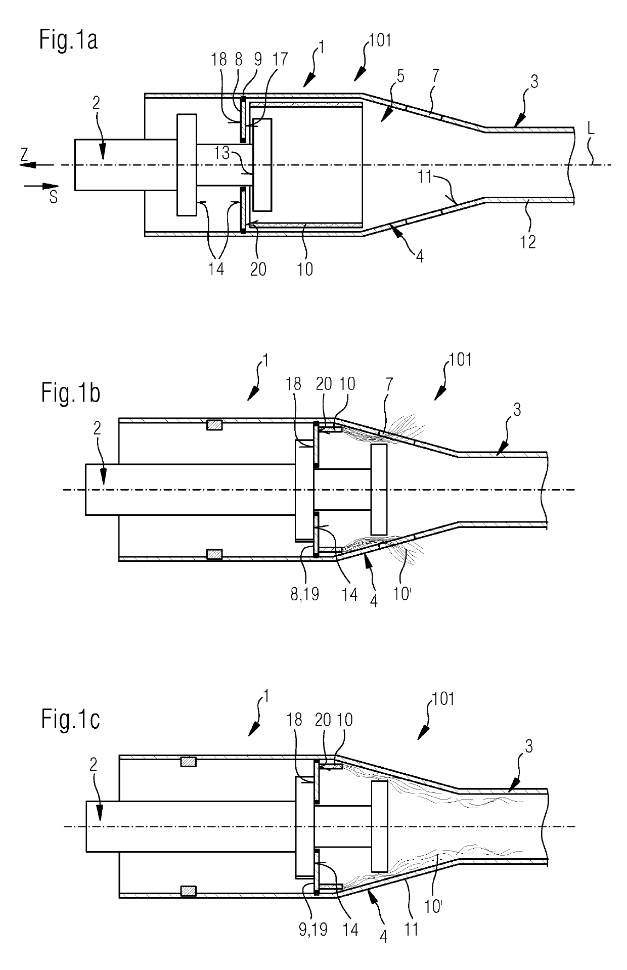
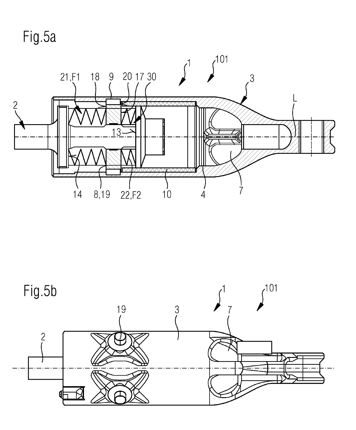
[0064]FIGS. 1a-5 show in a schematically simplified illustration the basic structure and the basic function of different embodiments of a traction-impact device 1 according to a The basic structure is identical, for which reason the same reference numerals are used for the same elements.

[0065]FIGS. 1a and 1b show in a schematically highly simplified illustration a first embodiment of a traction-impact device 1 according to the first embodiment in two functional positions. In this, the first force transmission element 2 is formed by a pull rod. The second force transmission element 3 is formed by a cylindrical element which extends along the longitudinal axis L with different cross-section regions. The cylindrical element surrounds in this instance an inner space when viewed in the peripheral direction about the longitudinal axis L. The nozzle portion 4 on the force transmission element 3 is formed either by the inner periphery 11 of the cylindrical element or by an additional compo...

second embodiment

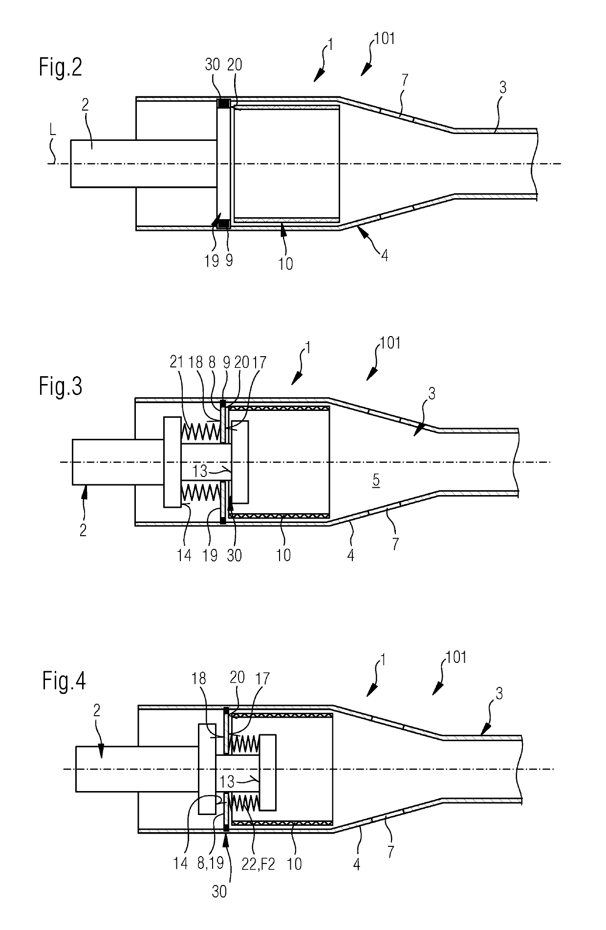
[0079]FIG. 10 shows, in contrast, a second embodiment in which the irreversible energy absorption element 10 is arranged on the outer periphery of the force transmission element 3. The coupling 30 of the first force transmission element 2 which is constructed as a pull rod, the traction and pressure stops 13, 14 and the coupling of the pressure plate 8 to the second force transmission element 3 and the arrangement of the energy absorption between the pressure plate 8 and pull rod are carried out as described in FIG. 5. The nozzle portion 4 is, however, integrated in the first force transmission element 2. To this end, it has a sleeve-like portion 26, which surrounds the force transmission element 3 in a peripheral direction.

[0080]When a maximum permissible impact force is exceeded, the force-transmitting connection 30 between the force transmission element 2 and 3 is also cancelled by way of response of the desired breaking locations 9 between the pressure plate 8 and counter-elemen...


PUM


Abstract

A traction-impact device including two force transmission elements which extend along a longitudinal axis and which are connected to each other in a force-transmitting manner and an irreversible energy absorption device that includes at least one energy absorption element which at least partially or in regions, preferably completely, includes a fiber composite material. The irreversible energy absorption device is at least partially received by a first of the two force transmission elements. This first force transmission element includes a nozzle portion. The irreversible energy absorption element is arranged in such a manner with respect to the nozzle portion and the other second force transmission element that, when an impact force which exceeds the maximum permissible impact force is introduced into the traction-impact device, the irreversible energy absorption element is pressed through the nozzle portion with at least partial, preferably complete defibration of the regions formed from fiber composite material.

Description

CROSS REFERENCE TO RELATED APPLICATIONS[0001]This is a continuation of PCT application No. PCT / EP2017 / 079598, entitled “TRACTION / IMPACT DEVICE AND FORCE TRANSMISSION UNIT HAVING SUCH A TRACTION / IMPACT DEVICE”, filed Nov. 17, 2017, which is incorporated herein by reference.BACKGROUND OF THE INVENTION1. Field of the Invention[0002]The present invention relates to rail-bound vehicles, and more particularly to a traction-impact device for a rail-bound vehicle.2. Description of the Related Art[0003]Force transmission units in the form of coupling rods, in particular for use in rail-bound vehicles for transmitting forces between a coupling head and a connection element for at least indirect connection to a carriage body, for example, a bearing block having traction-impact devices, are known in the prior art in different configurations. Such coupling rods can depending on requirements be provided with reversible and / or irreversible energy absorption in addition to the force transmission fu...

Claims


Application Information

Patent Timeline
IPC IPC(8): B61G11/16F16D3/62B61G7/10B61G11/18
CPCB61G11/16F16D3/62B61G7/14B61G11/18B61G7/10B61D15/06
Inventor RADEWAGEN, CHRISTIANKOLSHORN, KAY UWEROMUND, MATHIAS
Owner VOITH PATENT GMBH
Why Eureka
Try Eureka