Final Joint of Immersed Tunnel as well as Prefabrication Method and Installation Method

a technology of prefabrication and tunnel, which is applied in the field of final joint of an immersed tunnel, can solve the problems of reducing the risk of installation quality defects and reducing the number of open sea diving work, and achieves the effects of convenient control of position and posture, convenient installation and control, and simple structur

Active Publication Date: 2018-09-27
CHINA COMMUNICATIONS CONSTRUCTION +1
View PDF1 Cites 6 Cited by
  • Summary
  • Abstract
  • Description
  • Claims
  • Application Information

AI Technical Summary

Benefits of technology

[0069]1. According to the final joint of the immersed tunnel of the present application, the two end surfaces of the final joint are set as the tilted surfaces, so that the whole final joint is of the inverted trapezoid structure; and therefore, during immersed installation of a final tube head, its position and posture may be controlled conveniently, a risk of collision with the to-be-connected installed adjacent tube sections is lowered, and the final tube head enters the installation station conveniently. The tilted surfaces formed by the final joint may be connected with the installed adjacent tube sections in a matched manner to realize final installation construction. The final joint of the immersed tunnel is simple in structure, convenient to install and control and relatively high in precision. During installation, lots of open sea diving work may be further reduced, and the risk of installation quality defects is lowered;
[0070]2. According to the final joint of the immersed tunnel of the present application, the inverted trapezoid structure may be further formed by the tube section I and the tube section II, so that during immersed installation of the final tube head, its position and posture may be controlled conveniently, the risk of collision with the to-be-connected installed adjacent tube sections is lowered, and the final tube head enters the installation station conveniently. The tilted surfaces formed by the tube section I and the tube section II are matched with the installed adjacent tube sections, and then connection and installation construction is completed. The final joint formed by connecting the two tube sections is convenient to machine, and the space between the tube sections is further formed after subsequent assembly of the two tube sections, thereby facilitating subsequent installation construction of the seal doors;
[0071]3. According to the final joint of the immersed tunnel of the present application, the push devices are used for enabling the Gina water stop bands to be in contact with the surfaces of the installed adjacent tube sections and to realize water stop between the combination cavities and the outside after the Gina water stop bands are fully compressed during connection of the tube section I as well as the tube section II and the corresponding installed adjacent tube sections, thereby facilitating later water drainage of the combination cavities and forming the dry construction environment;
[0072]4. According to the final joint of the imm...

Problems solved by technology

During installation, lots of open sea diving work may be furt...

Method used


Image

  • Final Joint of Immersed Tunnel as well as Prefabrication Method and Installation Method
  • Final Joint of Immersed Tunnel as well as Prefabrication Method and Installation Method
  • Final Joint of Immersed Tunnel as well as Prefabrication Method and Installation Method

Examples


embodiment 1

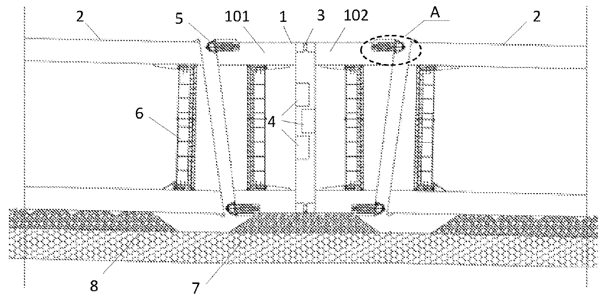
[0084]As shown in FIGS. from 1 to 4, a final joint 1 of an immersed tunnel includes a tube section I 101 and a tube section II 102 which are connected with each other. Connection surfaces, which are respectively connected with installed adjacent tube sections 2, of the tube section I 101 and the tube section II 102 are tilted surfaces, so that the tube section I 101 and the tube section II 102 jointly form an inverted trapezoid structure on the longitudinal profile along an installation direction; and water stop systems 5 connected with the installed adjacent tube sections 2 are disposed on the connection surfaces of the tube section I 101 and the tube section II 102.

[0085]As shown in FIG. 2, the tube section I 101 and the tube section II 102 adopt shell bodies. A plurality of transverse diaphragms and longitudinal diaphragms 10 are disposed in the shell bodies; all the transverse diaphragms and longitudinal diaphragms 10 divide the shell bodies of the tube section I 101 and the tub...

embodiment 2

[0097]The present application further provides a prefabrication method of a final joint 1 of an immersed tunnel, including:

[0098]Step I, respectively forming a shell body of a tube section I 101 and a shell body of a tube section II 102 according to shapes of the tube section I 101 and the tube section II 102;

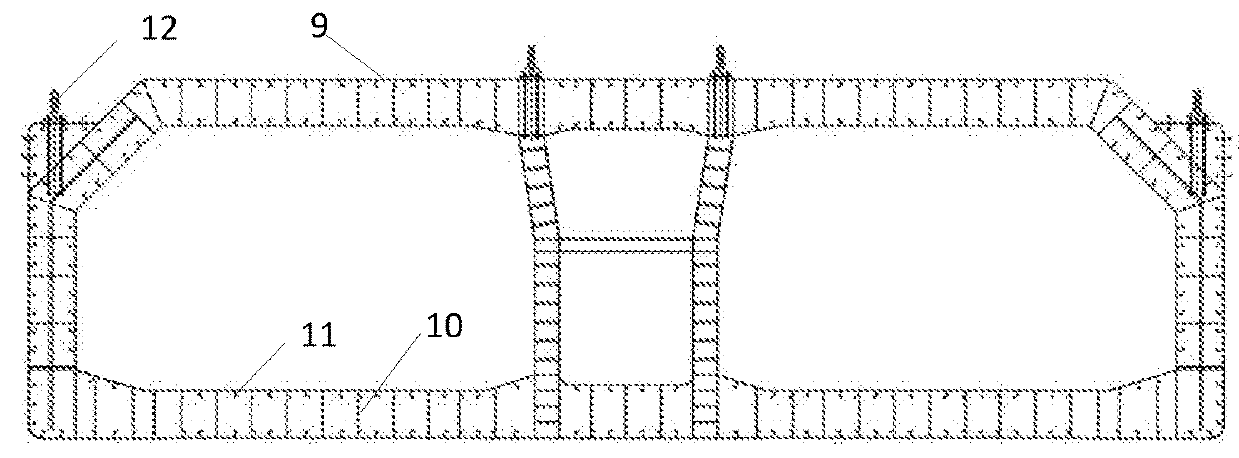
[0099]Step II, installing a plurality of transverse diaphragm and longitudinal diaphragms 10 in the shell body of the tube section I 101 and the shell body of the tube section II 102 to form a plurality of compartments, and forming pouring holes and exhaust holes in each compartment;

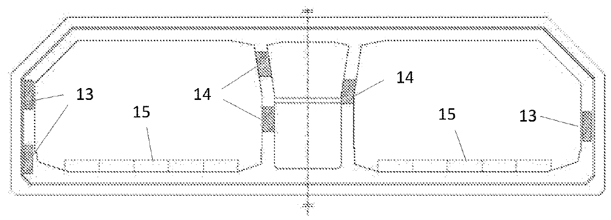
[0100]Step III, connecting the shell body of the tube section I 101 with the shell body of the tube section II 102, and performing tensioning and compression through prestressed tendons, wherein multiple bundles of steel strands are disposed at each of a top plate and a bottom plate of the final joint 1, two backup pipelines are respectively reserved on each of the top plate and the bottom plate, an...

embodiment 3

[0106]The present application further provides an installation method of a final joint 1 of an immersed tunnel, including:

[0107]Step I, prefabricating a tube section I 101 and a tube section II 102, and forming the final joint 1 of the immersed tunnel by adopting the above-mentioned prefabrication method of the final joint 1 of the immersed tunnel in Embodiment 2;

[0108]Step II, arranging tilted to-be-installed surfaces on two installed adjacent tube sections 2 to be connected with the tube section I 101 and the tube section II 102, respectively matching the two to-be-installed surfaces with connection surfaces of the tube section I 101 and the tube section II 102 in shape, and respectively installing end seal doors 6 in the tube section I 101, the tube section II 102 and the two installed adjacent tube sections 2, wherein outfitting work of the final joint 1 mainly includes in-tube outfitting members and tube-top outfitting members; the tube-top outfitting members mainly include gui...


PUM


Abstract

The present application discloses a final joint of an immersed tunnel, a prefabrication method and an installation method, wherein the final joint includes two end surfaces connected with installed adjacent tube sections; the two end surfaces are both tilted surfaces, so that the longitudinal profile of the final joint along an installation direction is of an inverted trapezoid structure; and the final joint further may be of a structure with a tube section I and a tube section II which are connected with each other. The final joint of the immersed tunnel is simple in structure, convenient to control and relatively high in precision, thereby reducing lots of open sea diving work and lowering a risk of installation quality defects; as prefabrication procedures are simple, the final joint may be prefabricated in a land factory and then transported to the site, thereby reducing influence of weather conditions on construction; a body structure of the final joint is prefabricated in the factory, and then the overall final joint is transported to the site for installation; water stop systems realize quick water stop, thus forming a dry construction environment; and therefore, the influence of weather and tidal current conditions on a project may be reduced, and a quality risk may be lowered.

Description

TECHNICAL FIELD[0001]The present application relates to the technical field of immersed tunnels, and more particularly relates to a final joint of an immersed tunnel, a prefabrication method of the final joint of the immersed tunnel, and an installation method of the final joint of the immersed tunnel.BACKGROUND ART[0002]Immersed tube method-based tunnel construction is to respectively transport tunnel caissons, which are prefabricated in a semi-submerged barge or a dry dock, in a floating manner to preset positions for immersion and jointing. In order to successfully immerse the last tube section, a distance space longer than the tube section must be reserved, and the tube section immersed and jointed in the reserved distance space is regarded as a final joint. The final joint of the immersed tunnel is crucial for construction of the immersed tunnel, particularly for construction of an open sea ultra-long immersed tunnel under severe site construction conditions, and complicated oc...

Claims


Application Information

Patent Timeline
IPC IPC(8): E02D29/073E02D29/16E02D29/07E02D29/067
CPCE02D29/073E02D29/16E02D29/07E02D29/067E02D2250/0061
Inventor LIN, MINGLIU, XIAODONGGAO, JIBINGLI, YIYIN, HAIQINGLIN, WEILV, YONGGANGDENG, KEWANG, QIANGCHENG, QIANLIU, LINGFENGJI, HAIZHANG, ZHIGANGSU, HUAIPINGWANG, XIAODONG
Owner CHINA COMMUNICATIONS CONSTRUCTION
Why Eureka
Try Eureka