

Battery pack
a battery module and battery technology, applied in the field of batteries, can solve problems such as the deterioration of battery cells in the battery modul
- Summary
- Abstract
- Description
- Claims
- Application Information
AI Technical Summary
Problems solved by technology
Method used
Image

Examples
embodiment 1
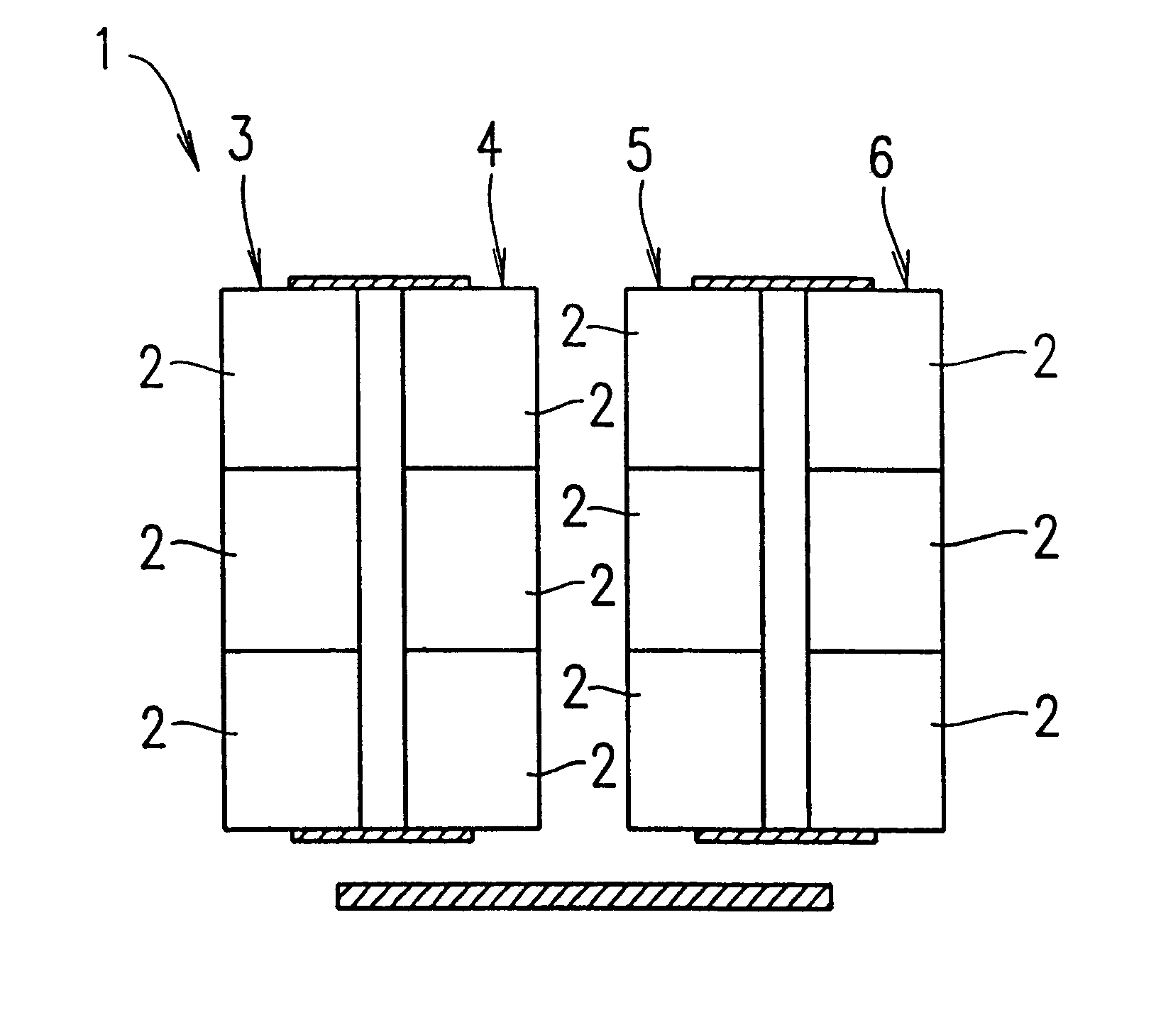
Hereinafter, Embodiment 1 of the present invention is described with reference to FIG. 1.
FIG. 1 schematically shows a structure of a substantial part of a battery pack 1 according to Embodiment 1 of the present invention. The battery pack 1 includes a pair of battery modules 3 and 4 and a pair of battery modules 5 and 6, each battery module including a plurality of battery cells 2 connected in series. The pair of the battery modules 3 and 4 are connected to each other in parallel. The other pair of the battery modules 5 and 6 are also connected to each other in parallel.
The pair of battery modules 3 and 4 are positioned in close vicinity to each other. The other pair of the battery modules 5 and 6 are also positioned in close vicinity to each other.
The pair of battery modules 3 and 4 connected in parallel are positioned in close vicinity to each other because as the distance between the battery modules 3 and 4 decreases, radiant heat is more easily transferred between the battery mo...
embodiment 2
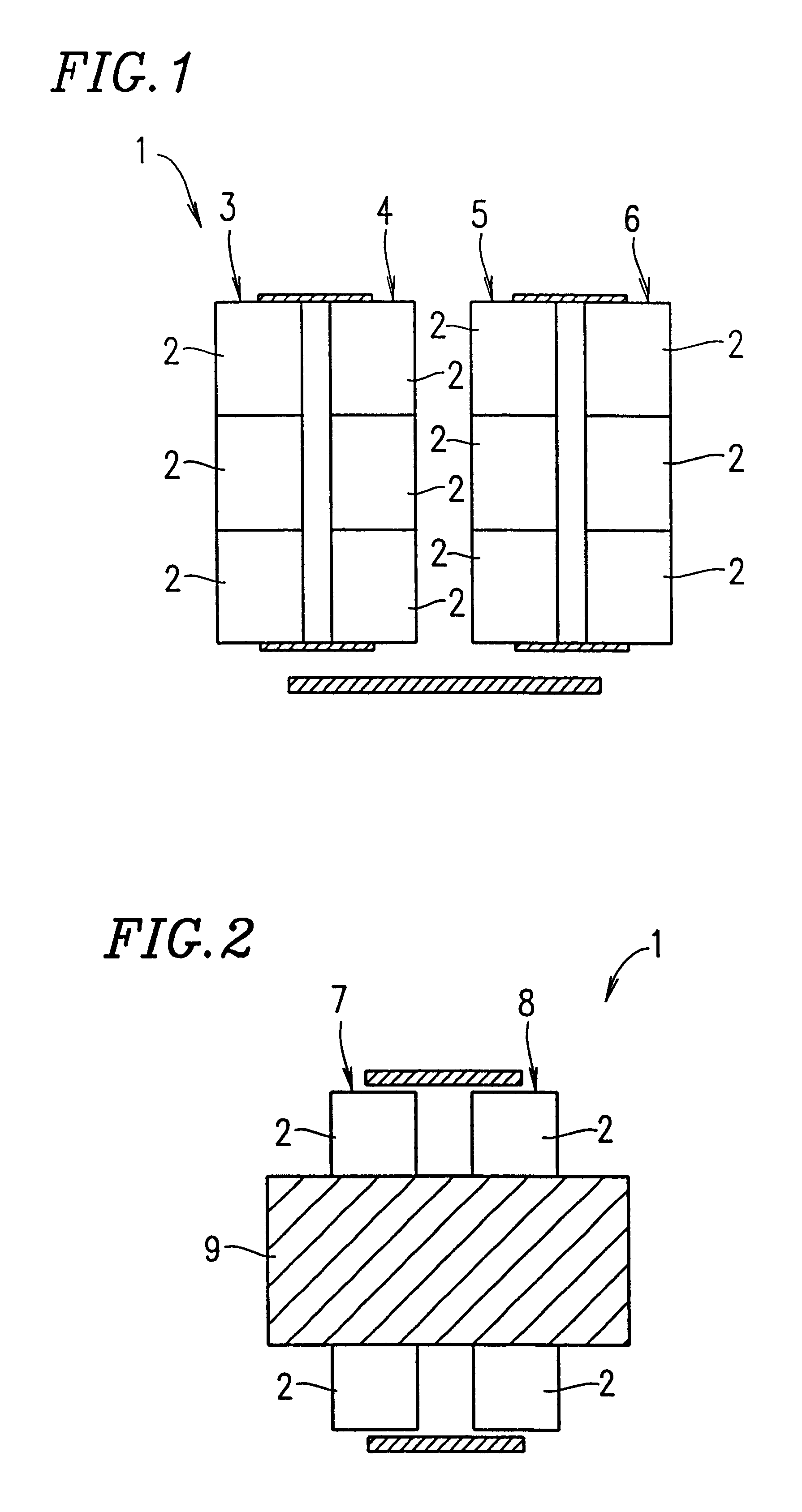
FIG. 2 schematically shows a structure of a substantial part of a battery pack 1 according to Embodiment 2 of the present invention. The battery pack 1 includes a pair of battery modules 7 and 8, each of the battery modules 7 and 8 including a plurality of battery cells 2 connected in series. The battery modules 7 and 8 are connected to each other in parallel.
In a central part of the battery modules 7 and 8, a high heat conductive member 9 is provided so as to bridge over the battery modules 7 and 8. The high heat conductive member 9 is formed of an aluminum plate, or the like.
With the high heat conductive member 9 provided over the battery modules 7 and 8, heat is conducted well between the battery modules 7 and 8. In such a structure, the difference in the temperature between the battery modules 7 and 8 is decreased. Therefore, the variation in the amount of electric power charged in the battery cells 2 of the battery modules 7 and 8 can be suppressed, and the state of charge of t...
embodiment 3
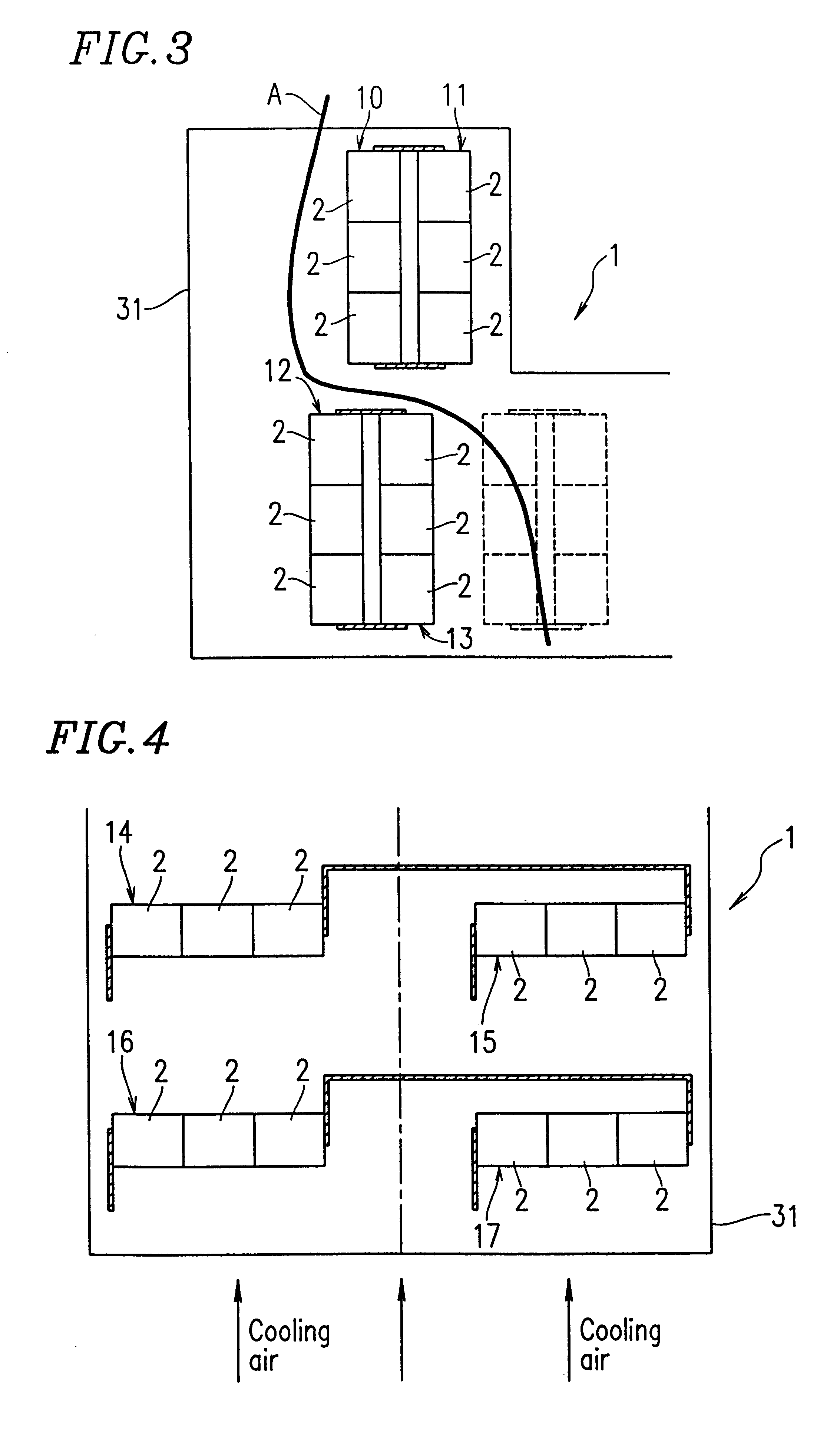
FIG. 3 schematically shows a structure of a substantial part of a battery pack 1 according to Embodiment 3 of the present invention. The battery pack 1 includes a pair of battery modules 10 and 11, each of the battery modules 10 and 11 including a plurality of battery cells 2 connected in series. The pair of battery modules 10 and 11 are connected to each other in parallel. The battery pack 1 further includes a pair of battery modules 12 and 13 connected to each other in parallel. The pair of battery modules 10 and 11 and the pair of battery modules 12 and 13 are contained in a case 31.
In the case 31, the pair of battery modules 10 and 11 are positioned in a region having a uniform cooling condition. Similarly, the other pair of battery modules 12 and 13 are positioned in a region having uniform cooling condition.
For example, when there is an isotherm A in the case 31 as shown in FIG. 3, the pair of battery modules 10 and 11 are positioned in the case 31 such that both are located i...
PUM
| Property | Measurement | Unit |
|---|---|---|
| shape | aaaaa | aaaaa |
| power | aaaaa | aaaaa |
| voltage | aaaaa | aaaaa |
Abstract
Description
Claims
Application Information