Drawer closing and latching system

Inactive Publication Date: 2003-01-28
INTERMETRO IND CORP
View PDF8 Cites 68 Cited by
  • Summary
  • Abstract
  • Description
  • Claims
  • Application Information

AI Technical Summary

Benefits of technology

The invention has the further object of enhancing the s

Problems solved by technology

Some of the medications are expensive, and some may be controlled substances, such as narcotics.
One problem with these prior art cabinets is that it is possible to leave one or more drawers slightly ajar, just beyond the reach of

Method used


Image

  • Drawer closing and latching system
  • Drawer closing and latching system
  • Drawer closing and latching system

Examples


Embodiment Construction

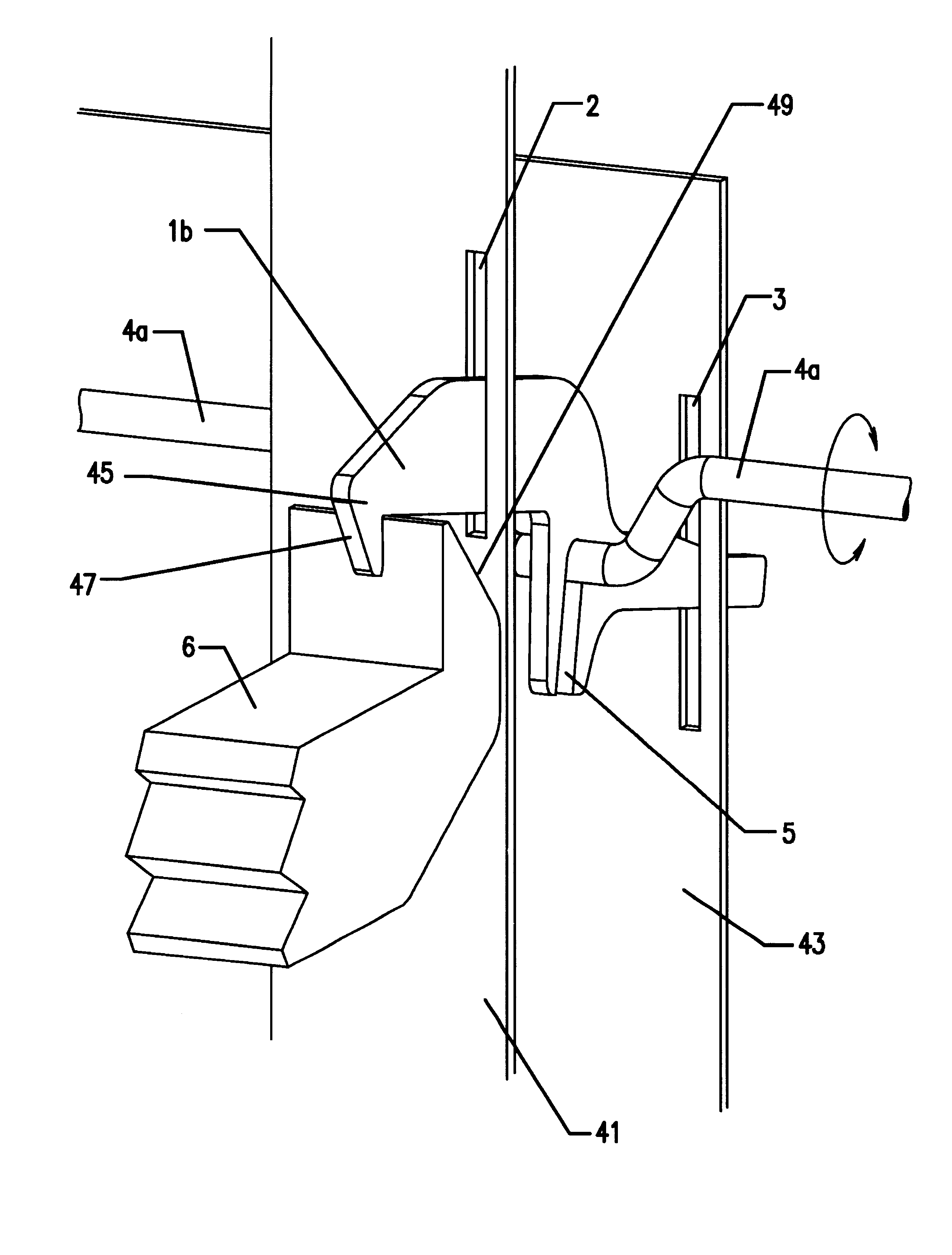
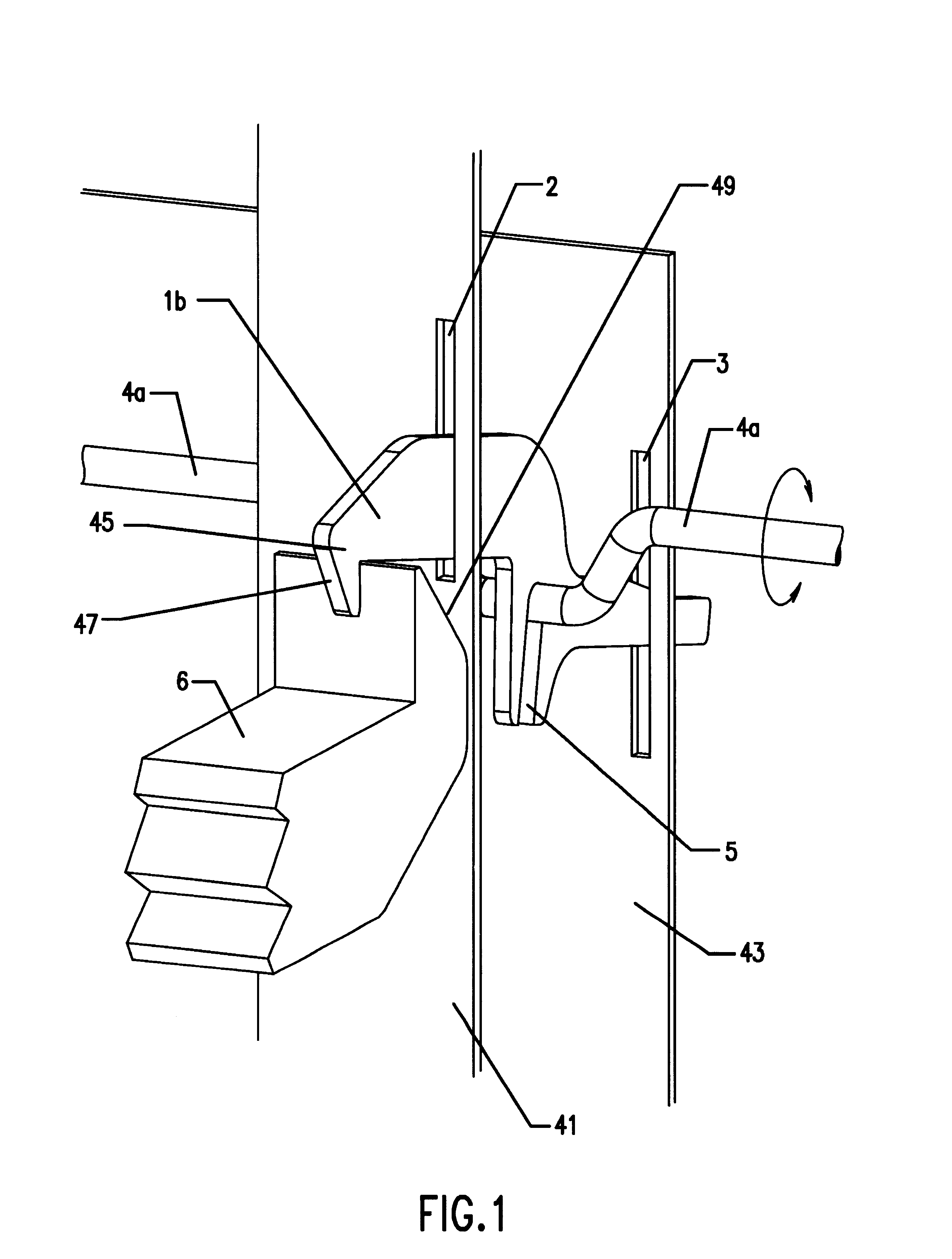
FIG. 1 provides a partial perspective view of one arrangement of the latch mechanism of the present invention. FIG. 1 shows a latch mechanism for a single drawer.

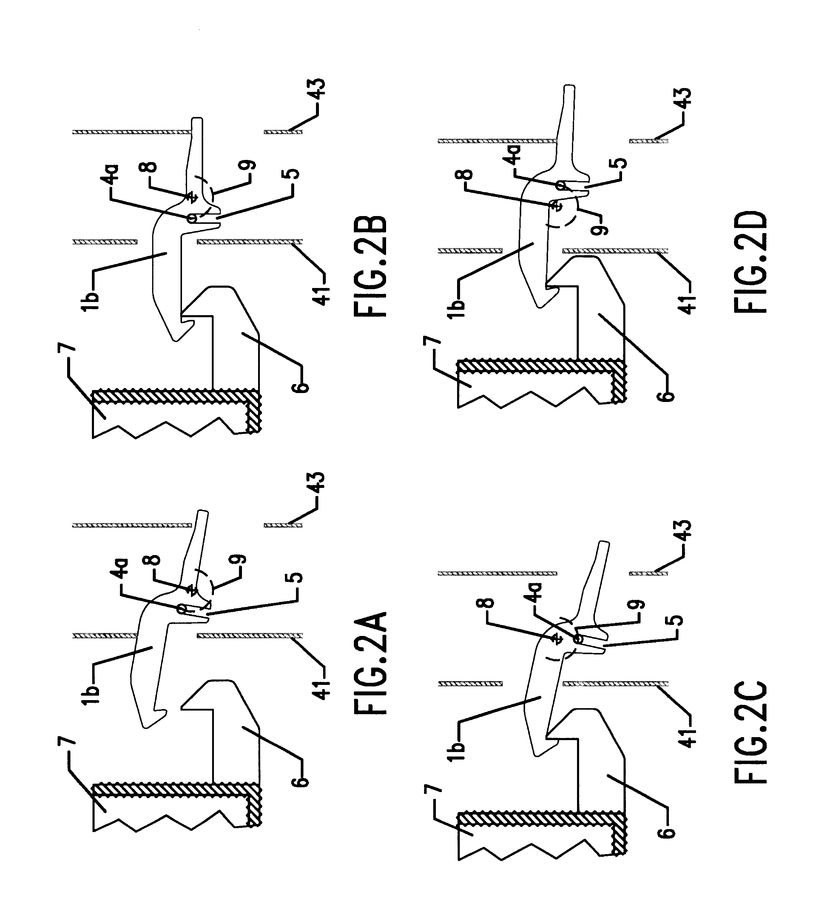
The latch mechanism includes latch finger 1b, which is constrained to move in openings 2 and 3 formed, respectively, in front plate 41 and rear plate 43. The openings allow the latch finger to move forward and backward freely. The openings have upper and lower ends which define limits for upward and downward movement of the latch finger. In the position shown, the hooked end 45 of the latch finger 1b engages catch 6 which is attached to the rear portion of drawer 7 (not shown in FIG. 1, but visible in FIGS. 2A-2D). Crankshaft 4a imparts motion to the latch finger by engaging slot 5 formed in the latch finger.

As crankshaft 4a rotates clockwise about its axis, from the position shown in FIG. 1, it raises latch finger 1b to the top of opening 2 in plate 41. In this raised position, the hooked end 45 of latch finger 1b is disen...


PUM


Abstract

A mechanical system closes and latches one or more drawers in a multiple-drawer cabinet. Drawers which are slightly ajar are grasped by the latching mechanism, pulled fully closed, and locked shut. A latch finger engages a catch connected to the drawer and pulls the drawer closed. The finger is actuated by a crankshaft which, as it rotates, first lowers the latch finger to capture the catch, and then retracts the latch finger and with it the captured drawer. The crankshaft rotates to a position where any pull forces on the finger are nearly in line with the axis of the crankshaft and have little tendency to cause reverse rotation. The crankshaft is then retained in this position, effectively locking the drawer closed. Thus, any drawer which is left slightly ajar, and which may falsely appear to be latched, is subsequently closed and securely locked. The latching mechanism may be motorized or manually operated. If motorized, a controller may actuate the mechanism to close and lock the drawers after some predetermined delay. Unlocking may be enabled by key or by security code entry. The locking capability of this system makes it particularly useful in controlling access to medications in a hospital environment or wherever expensive or potentially dangerous materials are stored.

Description

BACKGROUND OF THE INVENTIONThe present invention provides a system for latching, closing, and locking drawers in a cabinet.Hospitals and other health care facilities often use wheeled cabinets for storing medications and other supplies, and for transporting such medications and supplies from one patient to another. These cabinets generally have numerous drawers, in which many different types of medications may be kept separate within the cabinet. Some of the medications are expensive, and some may be controlled substances, such as narcotics. Thus, the security of the cabinet is important, and various governmental regulations, as well as rules of the particular institution, require that all drawers of such cabinets be locked when the cabinet is unattended.The prior art contains many examples of cabinets having manual or automatic means for locking drawers. One problem with these prior art cabinets is that it is possible to leave one or more drawers slightly ajar, just beyond the reac...

Claims


Application Information

Patent Timeline
IPC IPC(8): E05B65/46E05B65/44E05B17/00E05B53/00E05B47/00E05B65/462
CPCE05B65/462E05B17/0025E05B47/0012E05B2047/0025E05B53/003
Inventor GARDNER, JOHN F.SLOGOFF, SHELLY I.LAYCOCK, JANE F.NORLIN, ERIC C.WILLIAMS, E. FORDWILLIAMS, TOBIN H.
Owner INTERMETRO IND CORP
Why Eureka
Try Eureka