Distinctive hazard flash patterns for motor vehicles and for portable emergency warning devices with pulse generators to produce such patterns

a technology of flashing patterns and motor vehicles, which is applied in vehicle lighting systems, transportation and packaging, lighting and heating equipment, etc., can solve the problem that drivers are often not as quickly aware of hazards

Inactive Publication Date: 2003-02-04
J WINDY
View PDF8 Cites 50 Cited by
  • Summary
  • Abstract
  • Description
  • Claims
  • Application Information

AI Technical Summary

Benefits of technology

1) Create a hazard alert flash sequence with distinctive flash rates and patterns so that hazard signals can be quickly and easily distinguished from turn signals.
8) Provide pulse generating devices for emergency electric lanterns, illuminated emergency warning triangles, and electric replacements for pyrotechnic flares, which can produce the same or similar non-uniform hazard alert pattern as automotive hazard flashers, for improved recognition.
An application using exclusively LED's or other devices could make it practical and desirable to have different rates and / or patterns. The relatively long warm up and cool down time of incandescent bulbs limits how short the on time and the off time can be compared to LED's.

Problems solved by technology

Even when both flashing rear lights of al stopped or slow-moving vehicle are seen, because turn signals flashing at the same uniform rate are so commonplace, drivers often are not as quickly aware as they could be that they are seeing a hazard warning and not a turn signal.

Method used


Image

  • Distinctive hazard flash patterns for motor vehicles and for portable emergency warning devices with pulse generators to produce such patterns
  • Distinctive hazard flash patterns for motor vehicles and for portable emergency warning devices with pulse generators to produce such patterns
  • Distinctive hazard flash patterns for motor vehicles and for portable emergency warning devices with pulse generators to produce such patterns

Examples


Embodiment Construction

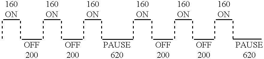
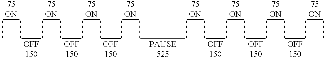
The hazard alert flasher described generates hazard warning flasher rates and patterns for highway vehicles and for highway emergency electric lanterns. A specific and unique flash pattern is intended to alert other motorists, at first sight, that they are seeing a hazard warning and not a turn signal. After numerous trials a signal consisting of three very short flashes followed by a pause has been selected for the automotive hazard alert flasher prototype.

The flash rate of the automotive prototype is designed to comply with the requirements of federal and stale laws and regulations. The standard adopted by the authorities is that of the Society of Automotive Engineers (SAE). SAE J945 provides that the hazard flash rate shall be 60 to 120 flashes per minute and the percent on time shall be 30% to 75%. The flash rate of the automotive prototype as programmed is 120 flashes per minute and 32% on time.

The flash rate and pattern used in the automotive prototype has been judged by the i...


PUM


Abstract

A flashing light sequence which is readily distinguished by drivers as the signal for a hazard alert as contrasted with turn signal flashes. An electronic hazard alert flasher unit is described which generates a hazard warning signal which is distinctively different in flash rate and pattern from standard turn signals and other on-off warning lights. One version of the hazard alert flasher unit is intended to replace the standard element presently used in highway vehicles to generate the turn signal and hazard flash pulse. A second version of the hazard alert flasher can be used to control the flash rate of free-standing emergency electric lanterns, illuminated emergency warning triangles, and LED substitutes for pyrotechnic flares. The proposed hazard alert flash pattern consists of three or more short flashes followed by a longer pause.

Description

1. Field of the InventionA motor vehicle hazard warning signal which is easily and quickly distinguished from a turn signal flash and which is more eye catching than the current hazard signal could make a significant contribution to highway safety if such improved hazard signal were widely used and thus recognized by drivers as the signal of a stopped or slow-moving vehicle.As presently designed, automobiles, trucks, and buses use the same flash rate and pattern for hazard flashers as is used for turn signals. A hazard flasher switch causes both the left and right lamps used for turn signals to flashing unison. This "four-way flash" is universally understood to be the hazard signal for a stopped or slow-moving vehicle. Because the hazard signal rate and pattern of flash at present is the same as the turn signal rate and pattern, the only way to distinguish a hazard flash from a turn signal flash is to observe that turn signal lights are flashing on both sides of the vehicle.Many pat...

Claims


Application Information

Patent Timeline
Patent Type & Authority Patents(United States)
IPC IPC(8): B60Q1/46B60Q1/26F21V23/04
CPCB60Q1/46F21W2101/12F21V23/0407F21W2103/20
Inventor DEYOUNG, JOHN W.
Owner J WINDY
Why Eureka
Try Eureka