Handheld optics detection system

a detection system and hand-held technology, applied in the field of collimated, monostatic, retroreflection-based optical systems, can solve the problems of not providing a retroreflection of sufficient energy intensity, and achieve the effects of high sensitivity, high sensitivity, and added clarity and contras

Inactive Publication Date: 2012-07-24
UNITED STATES OF AMERICA THE AS REPRESENTED BY THE SEC OF THE ARMY
View PDF1 Cites 12 Cited by
  • Summary
  • Abstract
  • Description
  • Claims
  • Application Information

AI Technical Summary

Benefits of technology

[0012]The present invention is an active imaging retroreflection based optical system for the detection of other optical systems, particularly “threat optics” such as sniper scopes, military grade binoculars, and digital targeting equipment. The active imaging system is switchable from either near-IR illumination, to a combination of near-IR and visible light illumination. The illumination is shaped into narrow elongated beams, generally elliptical in shape. The beams are channeled by rhomboid prisms so as to be emitted collimated to each other and monostatic relative to the detector; the prisms effectively locate the emitting aperture of the lasers near the center of the collecting aperture of the detector. The return image is resolved and refined by a series of objective and field lenses, and by a dual band, visible light and near-IR, pass filter, to add clarity and contrast. It is further enhanced by being amplified by a highly sensitive detector, such as a third generation imager; or a high sensitivity, back-illuminated CCD (charge coupled device); or a high sensitivity wide dynamic range CMOS (complimentary metal-oxide semiconductor) sensor. The retroreflected image, processed by this third generation imager, or the like, appears as a concentrated point of light, or bright spot, that can be quickly and easily distinguished from its surroundings, which also appear to the user.

Problems solved by technology

Alternative wavelength lasers, such as mid-range IR, do not provide a retroreflective return of sufficient energy intensity from the optics being observed to ensure quick and easy detection.

Method used


Image

  • Handheld optics detection system
  • Handheld optics detection system
  • Handheld optics detection system

Examples


Embodiment Construction

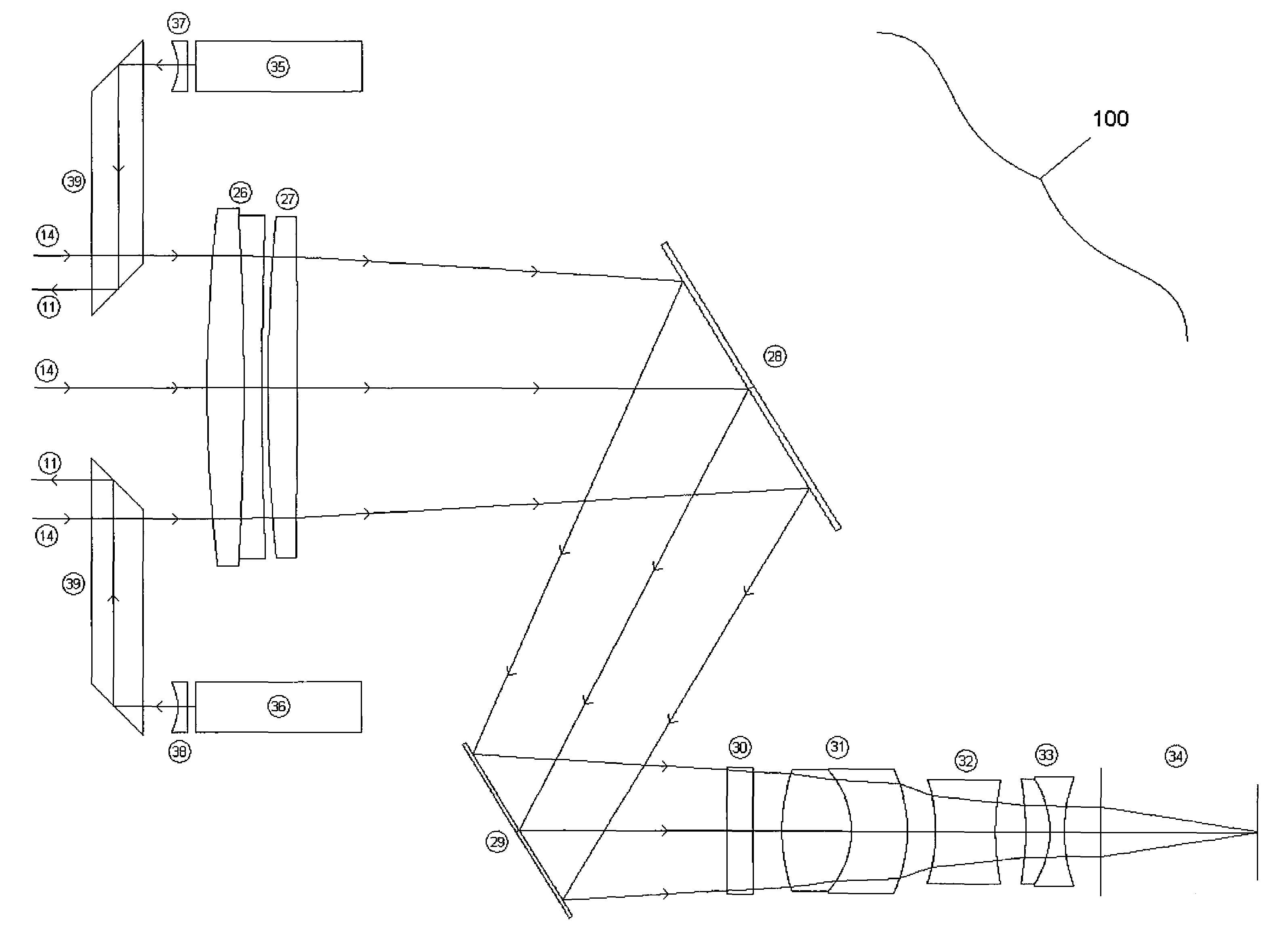
[0021]A first embodiment of the present active imaging retroreflection detection system 100 invention, for the detection of optical systems, such as sniper scopes (hereinafter “target”), is shown schematically in FIG. 3. The present invention is switchable by the user to emit either a single, or a set of two laser beams, i.e. a near-IR laser beam, generated by a first near IR laser 35, or a combination of this near-IR beam and a second visible light laser 36. The switching system, which is well known in the art, is not shown in FIG. 3. These beams are shaped by diverging lenses, wedge prisms, and / or cylindrical lenses 37, 38 into narrow, elongated, generally elliptical in shape sensing beams 11, to maximize the power of the retroreflected beam (as discussed below), as well as, to limit the field of view, as to focus the users attention on and localize targets. The sensing beams 11 from the lasers 35, 36 are channeled by rhomboid prisms to be emitted collimated to each other and gene...


PUM

PropertyMeasurementUnit
wavelengthaaaaaaaaaa
optical densityaaaaaaaaaa

Abstract

An active imaging retroreflection based optical system for the detection of other optical systems, especially passive optics used for observation/surveillance, or targeting. The active imaging system is switchable from either near-IR laser illumination, to a combination of near-IR and visible laser light illumination. The illumination is shaped into narrow elongated beams, generally elliptical in shape. These beams are channeled by rhomboid prisms so as to be emitted collimated to each other and monostatic to the detection system, such that the retroreflected return image returns axially to the optical detection system. The return image is resolved and refined by a series of objective and field lenses, and by a dual band, visible light and near-IR, pass filter, to add clarity and contrast. The energy is further enhanced by being amplified by a highly sensitive detector, such as a third generation imager; or a high sensitivity, back-illuminated CCD (charge coupled device); or a high sensitivity wide dynamic range CMOS (complimentary metal-oxide semiconductor) sensor. The retroreflected energy, processed by this third generation imager, or the like, appears as a concentrated point of light, or bright spot, that can be quickly and easily distinguished from its surroundings, which also appear to the user.

Description

CROSS-REFERENCE TO RELATED APPLICATIONS[0001]This application claims the benefit under 35 USC §119(e) of U.S. provisional patent application 61 / 060,215, filed on Jun. 10, 2008, which provisional application is hereby incorporated by reference.FEDERAL RESEARCH STATEMENT[0002]The inventions described herein may be manufactured, used, and / or licensed by the U.S. Government for U.S. Government purposes.FIELD OF THE INVENTION[0003]The present invention relates to a collimated, monostatic, retroreflection based optical system for detecting optical devices, and more particularly the detection of sniper and other threat optics using a highly sensitive detection system.BACKGROUND OF THE INVENTION[0004]One of the most common ways to classify imaging systems is as to whether they are “passive” or “active.” Classical Galilean and Keplerian telescopes, and binoculars, are passive systems, which gather ambient light to magnify the image of objects of interest. Such systems are for surveillance an...

Claims


Application Information

Patent Timeline
Patent Type & Authority Patents(United States)
IPC IPC(8): G02F1/153G06K7/10
CPCG02F1/153G06K7/10G02B23/00F41G3/14F41G3/147G01S7/4812G01S17/88G01S17/89G02B13/146G02B19/0085G02B27/0911G02B27/126G01S17/04
Inventor TOWERS, ROSSBUPATHI, DEEPAK
Owner UNITED STATES OF AMERICA THE AS REPRESENTED BY THE SEC OF THE ARMY
Why Eureka
Try Eureka