Method and apparatus which compensates for channel distortion

a channel distortion and channel compensation technology, applied in the field of digital tv systems, can solve the problems of system performance degradation, insufficient training sequence, and insufficient training sequence to remove moving ghosts

Inactive Publication Date: 2003-02-04
LG ELECTRONICS INC
View PDF10 Cites 188 Cited by
  • Summary
  • Abstract
  • Description
  • Claims
  • Application Information

AI Technical Summary

Problems solved by technology

However, when a moving ghost is loaded on the channel, the training sequence is not sufficient to remove a moving ghost because the state of the received signal would changes constantly.
Accordingly, the conventional method of removing the ghost existing in the channel using only the training sequence cannot effectively cope with the moving ghost in the channel, resulting in a deterioration in the performance of the system.

Method used


Image

  • Method and apparatus which compensates for channel distortion
  • Method and apparatus which compensates for channel distortion
  • Method and apparatus which compensates for channel distortion

Examples


first embodiment

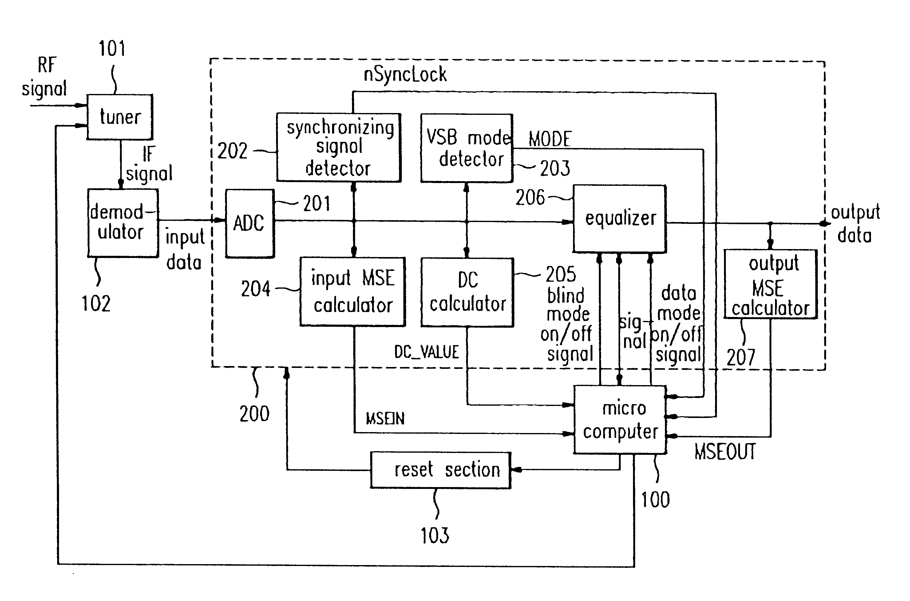
Upon the completion of initialization, the microcomputer 100 judges if the signal nSyncLock output from the synchronizing signal detector 202 is `0` (step 502). When it corresponds to `0`, meaning that both the data segment synchronizing signal and field synchronizing signal are detected, the process goes to step 504 for checking if the moving ghost exists. When the signal nSyncLock is `1`, meaning that the synchronizing signals are not detected, the channel decoder 200 and the tuner 101 of FIG. 5 are reset, to restart the process from the beginning (Step 503). Similar to the first embodiment, this operation is performed on assumption that a signal nSyncLock of `0` is generated when the synchronizing signal detector 202 detects both the data segment synchronizing signal and field synchronizing signal, and a signal nSyncLock of `1` is generated otherwise.

When the signal nSyncLock is judged to be `0` in step 502, the DC calculator 205 calculates the DC value loaded in the 10-bit digit...

third embodiment

FIGS. 12A and 12B show the present invention. Only portions of FIG. 12A, which are different from FIG. 11A, will be described below. Referring to FIGS. 11A and 11B, the process goes to the step of judging if the moving ghost exists when the value of the counter_1 which indicates how many times the microcomputer 100 reads the DC value from DC calculator 205 does not correspond to `10`. In FIG. 12A, however, the process returns to step 604 to repeat the operation of reading the DC value until the value of the counter_1 becomes `10` when the microcomputer 100 did not read the DC value ten times, i.e. when Counter_1.noteq.10. According to an experimental result obtained by realizing the algorithm of FIGS. 11A, 11B, 12A and 12B, the performance of the system by the process of FIGS. 11A and 11B is similar to that by the operation of FIGS. 12A and 12B.

fourth embodiment

FIGS. 13A and 13B show the present invention. Only portions of FIGS. 13A and 13B, which are different from FIGS. 11A and 11B, will be described below. There may be various methods for storing values in the memory[20]-memory[1]. In FIG. 11A, the minimum values of the DC values read by the microcomputer 100 ten times is stored in the memory[20]-memory[1]. In FIG. 13A, however, the average value of the DC values read by microcomputer 100 ten times is stored in the memories. For this, when the value of the counter_1 corresponds to `10` in step 705, this value is reset to `0`, and then the maximum value (maximum DC_Value) and minimum value (minimum DC_Value) of the ten DC values stored in within the memory of the microcomputer 100 are separately stored in parameters DCmax and DCmin while the average value of them is stored in a parameter DCvar (step 706).

Thereafter, the twenty memory value set in initialization step 701 shift one by one (step 707). That is, the value of the memory[19] sh...


PUM


Abstract

A method and apparatus for compensating for channel distortion is disclosed. In the present invention, equalization is performed in the treating sequence mode when the moving ghost does not exist in the channel and there is no possibility that the equalizer diverges, the data mode is cancelled and the equalization is carried out in the blind mode when the moving ghost does not exist in the channel but there is a possibility that the equalizer diverges, the equalizer is executed in the data mode when there is no possibility that the equalizer diverges but there exists the moving ghost including slowly moving ghosts in the channel, and the equalization is performed in the data mode and blind mode when the moving ghost exists and there is a possibility that the equalizer diverges.

Description

1. Field of the InventionThe present invention relates to a digital TV system, and more particularly to a method and apparatus for compensating channel distortion in the digital TV system.2. Discussion of Related ArtGenerally, a digital TV system removes ghost signals generated in a channel using the equalizer. Specifically, in the digital TV system, the received signal includes a training sequence signal in a field synchronous section of each field to help a receiver perform equalization. The receiver compensates for distortion generated in the channel using the training sequence. FIG. 1 shows the structure of one frame of a conventional digital TV signal and FIG. 2 shows a structure of the field synchronizing signal of FIG. 1.Referring to FIG. 1, a frame includes two fields. Each field has 313 data segments where one including one field synchronous segment containing the training sequence signal and 312 general data segments. Also, each data segment consists of a 4 symbol data seg...

Claims


Application Information

Patent Timeline
Patent Type & Authority Patents(United States)
IPC IPC(8): H04N5/21
CPCH04N5/211
Inventor NAM, HO JUN
Owner LG ELECTRONICS INC
Why Eureka
Try Eureka