Clip arrangement for garment hangers

Inactive Publication Date: 2003-02-11
UNIPLAST IND
View PDF11 Cites 53 Cited by
  • Summary
  • Abstract
  • Description
  • Claims
  • Application Information

AI Technical Summary

Problems solved by technology

The opposing (inner) side of the receiving slot of these pri

Method used


Image

  • Clip arrangement for garment hangers
  • Clip arrangement for garment hangers
  • Clip arrangement for garment hangers

Examples


Embodiment Construction

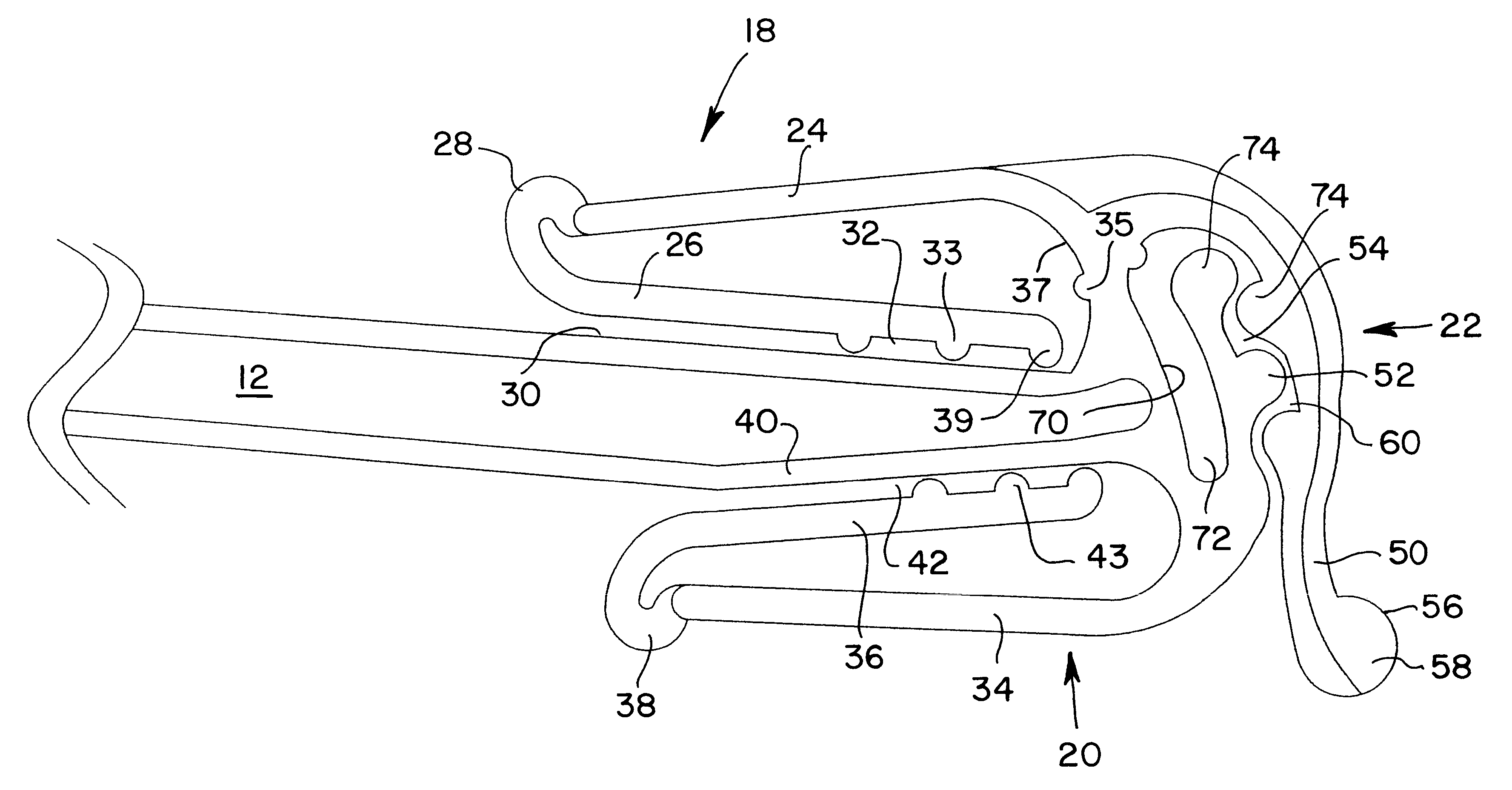
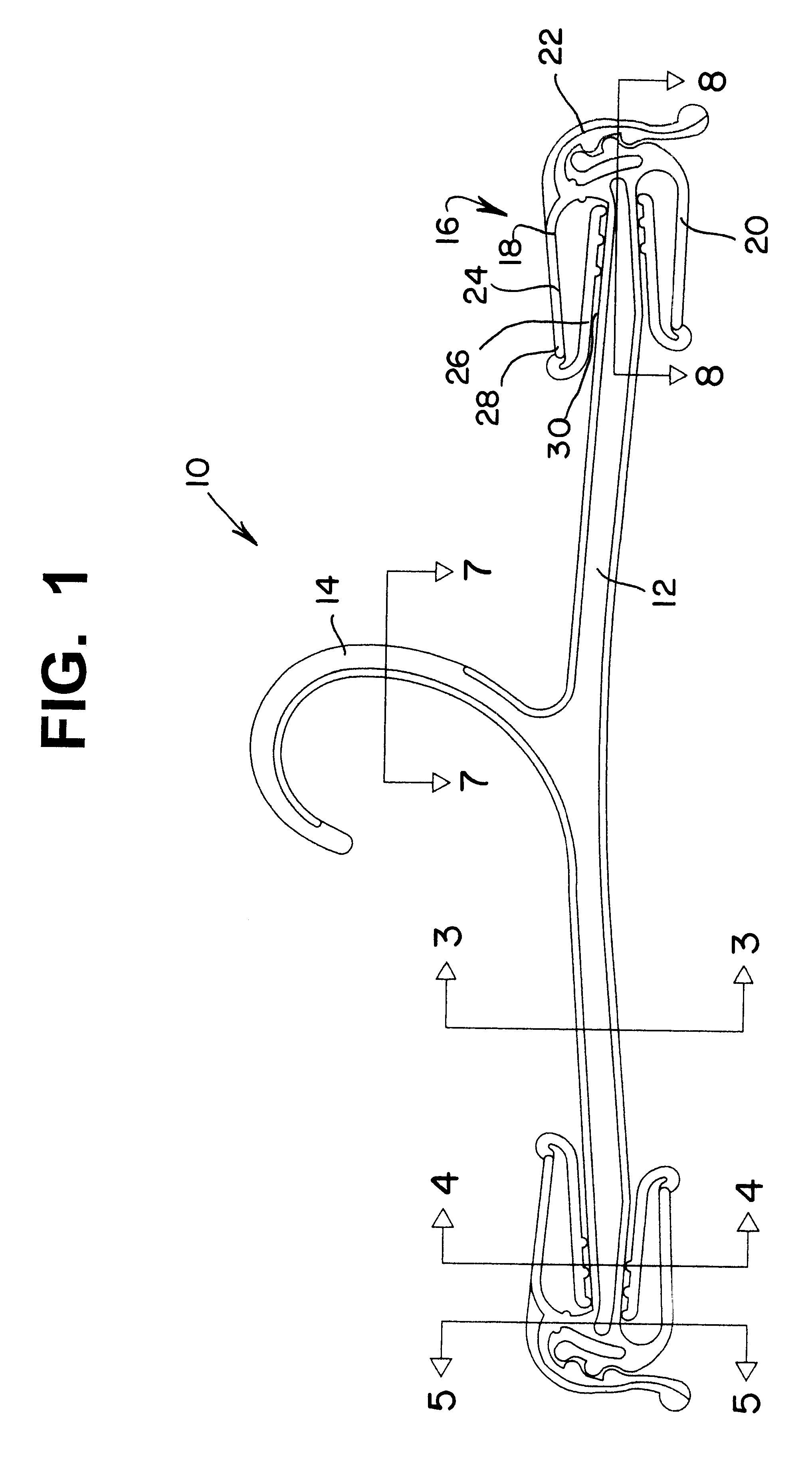
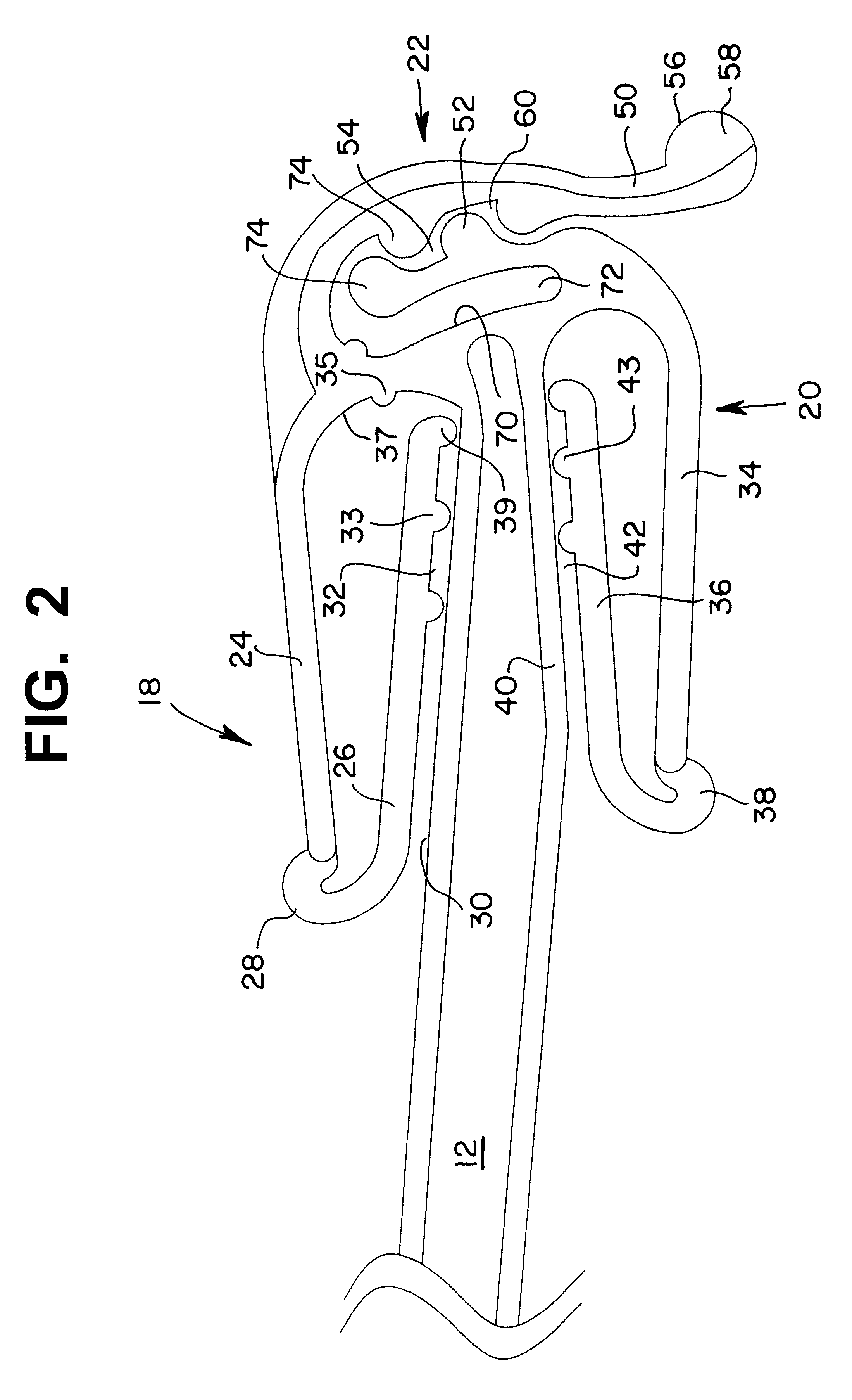
Referring to FIGS. 1 through 11, a garment shipping hanger 10, according to one embodiment, is shown. Garment hanger 10 includes a body portion 12 having two opposing ends and a hook member 14 integrally molded to body portion 12. The hook member 14 is generally positioned at a midpoint along body portion 12. The hanger 10 includes a clip assembly 16 integrally molded to body portion 12 and located at each opposing end of body portion 12. Garment shipping hanger 10 is preferably made as a single piece, molded in plastic using a plastic injection molding machine, as is understood by those skilled in the art. Any appropriate plastic may be used, such as styrene, which provides a clear, virtually transparent hanger. Alternatively, the hanger may be molded using polypropylene, such as H.I. styrene polypropylene, polypropylene, polyvinyichloride, ABS or other suitable thermoplastics and / or mixtures thereof. As understood by those skilled in the art, the plastic mixture used to mold the h...


PUM


Abstract

A garment hanger is provided and includes an elongated body, an integrally formed, centrally located hook member, and clip assemblies located at each opposing end of the body. Each clip assembly includes a horizontal lower clip, a horizontal upper clip and a vertical end clip. Each vertical clip includes a downwardly directed anchor arm which is spaced a predetermined distance from an inner surface of the end of the hanger and defines a receiving slot therebetween, into which clothing may be selectively inserted. The inner surface of the receiving slot includes an integrally formed upwardly and outwardly directly spring arm which is spring biased against an inside contact surface of the rigid anchor arm. It is the resiliency of this spring arm that creates a clamping action within the receiving slot which is used to force any inserted clothing snugly against the anchor arm, thereby holding the clothing in place within the receiving slot. The resiliency also permits the spring arm to flex inwardly toward the hanger body during garment insertion.

Description

1. Field of the InventionThe present invention relates generally to molded plastic hangers which are commonly used to ship and display lightweight clothing, such as undergarments, e.g., underwear, bathing suits, brasiers, etc. Garment hangers of this type typically include an elongated hanger body, a hook, and at least one clip located at each end of the elongated body. This invention relates more particularly to a clip structure used to hold one or more garments to the hanger body.2. Description of the Prior ArtThere have been many different types of plastic garment hangers used to hold lightweight garments. U.S. Pat. No. 6,196,430 to Gouldson discloses a plastic garment hanger which has an elongated body, an integrally formed hook, and two opposing integrally formed clip assemblies located at each end of the body. Each clip assembly includes a horizontal lower clip, a horizontal upper clip and a vertical end clip. The horizontal lower and upper clips have a similar structure inclu...

Claims


Application Information

Patent Timeline
IPC IPC(8): A47G25/48A47G25/00
CPCA47G25/48
Inventor GOLDMAN, ALLAN JOEL
Owner UNIPLAST IND
Why Eureka
Try Eureka