
Apparatus for lighting spaces, bodies or surfaces

a technology for lighting spaces and accessories, applied in the direction of fixed installation, vehicle lighting systems, lighting and heating equipment, etc., can solve the problems of high electrical actuation costs and significantly lower current consumption in comparison

Inactive Publication Date: 2003-02-18
DIEHL LUFTFAHRT ELEKTRONIK
View PDF17 Cites 72 Cited by
  • Summary
  • Abstract
  • Description
  • Claims
  • Application Information

AI Technical Summary

Benefits of technology

narrow lights are possible. which nonetheless produce a sufficiently large light spot.

Problems solved by technology

The use of light emitting diodes in the spot light sources makes it unnecessary to involve expensive electrical actuation of the cabin lighting.
Furthermore the current consumption is considerably lower in comparison with the use of conventional incandescent lamps.

Method used


Image

  • Apparatus for lighting spaces, bodies or surfaces
  • Apparatus for lighting spaces, bodies or surfaces
  • Apparatus for lighting spaces, bodies or surfaces

Examples


Embodiment Construction

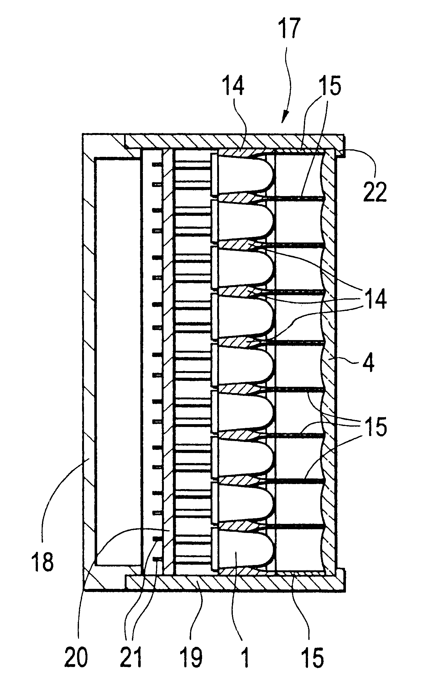
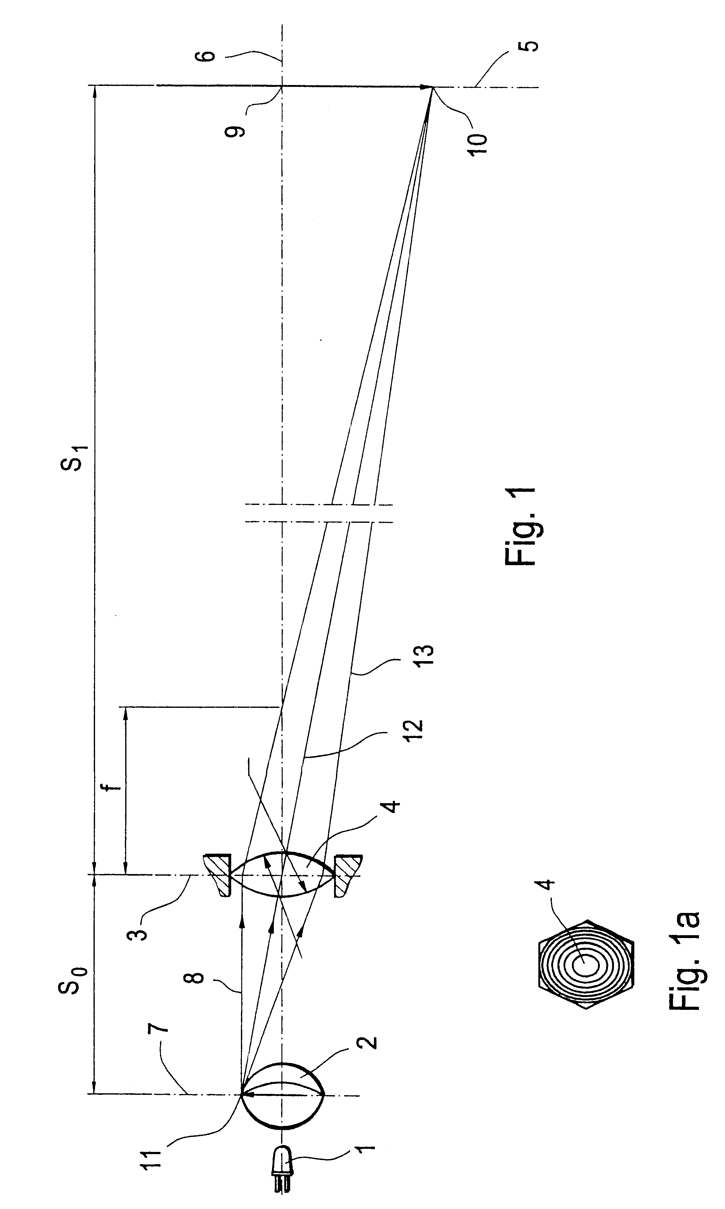
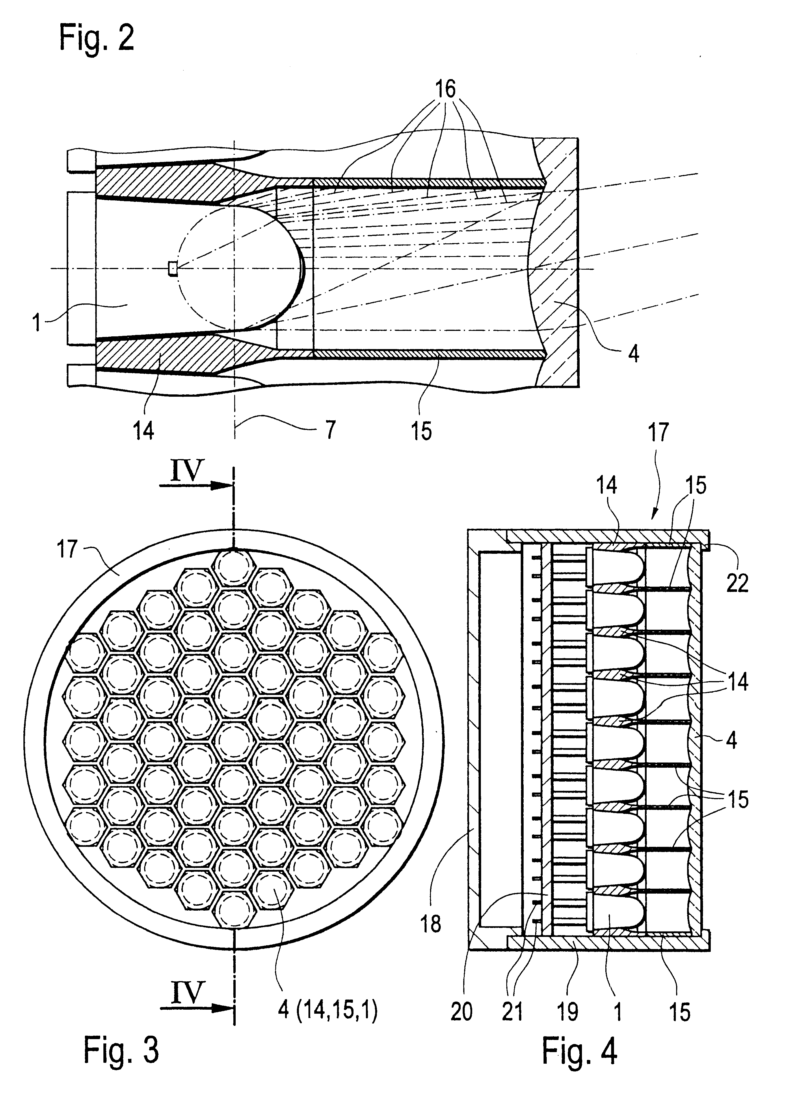
In the theoretical model for representing the optical beam path for a reading light the lightsource which in accordance with the invention is a light emitting diode is identified by reference 1. The light emitting diode 1 has a front, substantially spherical light exit surface 2. In an advantageous use of the invention, preferably narrowly focusing light emitting diodes 1 (LEDs) are employed. A lens 4 is disposed in a main plane 3, at a selectable and adjustable spacing relative to the object plane 7 of the light emitting diode 1. Shown at a further adjustable spacing in front of the lens 4 with the main plane 3 is the focal plane 5 which, like the main plane 3, is arranged perpendicularly to the optical beam path 6. The spacing between the object plane 7 of the light emitting diode 1 and the main plane 3 of the lens 4 is identified by S.sub.0 while the spacing between the main plane 3 of the lens 4 and the focal plane 5 is denoted by reference S.sub.1. The ratio of the spacings S.s...


PUM


Abstract

An apparatus for lighting or illuminating spaces, bodies or surfaces, which is formed from a plurality of light emitting diodes (1). The light emitting diodes (1) are radially enclosed by a casing body (14) which is adjoined at the end by a tubular element (15) which bears against a lens (4). A set spacing is thereby established between the light emitting diode (1) and the lens (4). All light spots issuing from the light emitting diode (1) are projected to form a single light spot of a high level of brightness by virtue of the superimposed relationship at a spacing in front of the lens (4).

Description

1. Field of the InventionThe invention concerns an apparatus for lighting or illuminating spaces, bodies or surfaces, in particular such as a reading light for aircraft, including at least one light source in the form of a white light emitting diode or a luminescence conversion diode, which is connected to a power supply unit.2. Discussion of the Prior ArtThe applicants' earlier German patent application DE 198 43 330.1 which has hitherto not been published describes an aeroplane cabin lighting arrangement which comprises a plurality of spot-like light sources. Those spot light sources have at least one light emitting diode and are connected to at least one power supply unit. The arrangement of a plurality of spot light sources at or in the ceiling of the cabin of an aircraft provides for uniform illumination of the cabin. The use of light emitting diodes in the spot light sources makes it unnecessary to involve expensive electrical actuation of the cabin lighting. Furthermore the c...

Claims


Application Information

Patent Timeline
Patent Type & Authority Patents(United States)
IPC IPC(8): F21V8/00F21V13/00F21V13/02F21V5/04
CPCF21V5/04F21V13/02G02B6/0006F21W2101/08F21Y2101/02F21W2101/06F21Y2115/10F21W2107/30F21W2106/00
Inventor BEYERLEIN, WOLFGANGKRUMMER, THOMAS
Owner DIEHL LUFTFAHRT ELEKTRONIK
Learn More