Control apparatus and control method for a construction machine

a construction machine and control apparatus technology, applied in agricultural machines, applications, instruments, etc., can solve the problems of deteriorating working efficiency, inability to perform 2 and inability to input unique information of the attached attachment 2 to the control apparatus

Inactive Publication Date: 2003-02-18
CATEPILLAR SARL
View PDF10 Cites 40 Cited by
  • Summary
  • Abstract
  • Description
  • Claims
  • Application Information

AI Technical Summary

Benefits of technology

Due to such a construction as described above, there is an advantage that, although discrimination failure display is performed by the display section if unique information of an attachment attached to the construction machine body cannot be inputted to the control section and the control section fails to discriminate the type of the attachment, also in this instance, a standard set value regarding an operation condition suitable for the attached working attachment can be set by a simple operation and with certainty by the standard set value setting section. Consequently, a hydraulic power source can be controlled based on information of the standard set value, and the working attachment can be operated in an appropriate operation condition.
Due to such a construction as just described, it can be confirmed by an operation of the confirmation switch that a correct confirmation condition of the working attachment has been set, and control of the hydraulic power source is started after the switch operation by the confirmation switch is confirmed by the control section. Consequently, there is an advantage that, even if the control section discriminates the type of the working attachment in error because of some disconnection or the like, inappropriate hydraulic power source control is prevented from being performed.
Due to such a construction as just described, since a standard set value is selected in accordance with the priority order, there is an advantage that setting of a standard set value by an operator can be performed smoothly.
Due to such a construction as just described above, there is an advantage that, since the standard set value can be changed by the standard set value changing means, an operation condition more suitable to the attached working attachment can be set.
Due to such a construction as described above, there is an advantage that, although discrimination failure display is performed by the display section if unique information of an attachment attached to the construction machine body cannot be inputted to the control section and the control section fails to discriminate the type of the attachment, also in this instance, a standard set value regarding an operation condition suitable for the attached working attachment can be set by a simple operation and with certainty by the standard set value setting section. Consequently, a hydraulic power source can be controlled based on information of the standard set value, and the working attachment can be operated in an appropriate operation condition.

Problems solved by technology

This operation is cumbersome and incidentally deteriorates the working efficiency.
However, in case a failure in contact or the like occurs with the control system, the type of the attachment 2 may be discriminated but in error or a wrong operation condition may be set for the attachment 2.
Further, if the control system suffers from some disconnection or a like trouble, unique information of the attachment 2 attached may not be inputted to the control apparatus.
However, only if discrimination failure display is performed on the display apparatus, discrimination of the type of the attachment 2 or setting of an operation condition of the attachment 2 cannot be performed, and no essential solution can be obtained.

Method used


Image

  • Control apparatus and control method for a construction machine
  • Control apparatus and control method for a construction machine
  • Control apparatus and control method for a construction machine

Examples


first embodiment

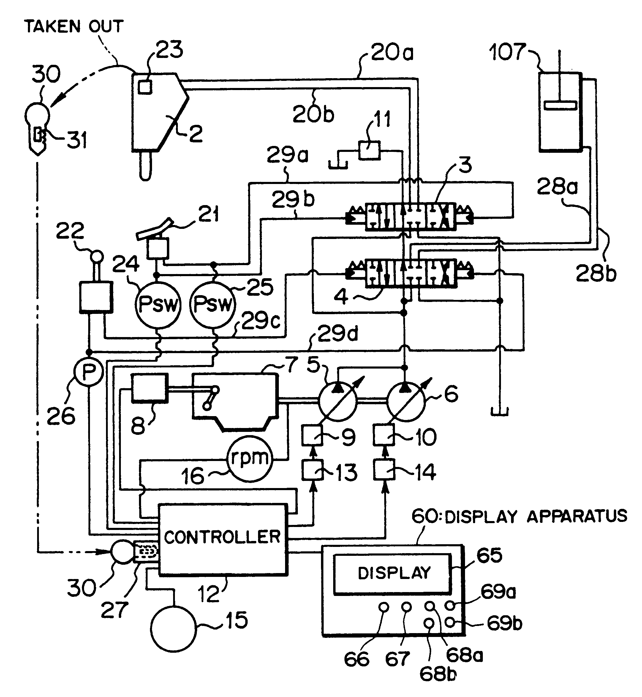
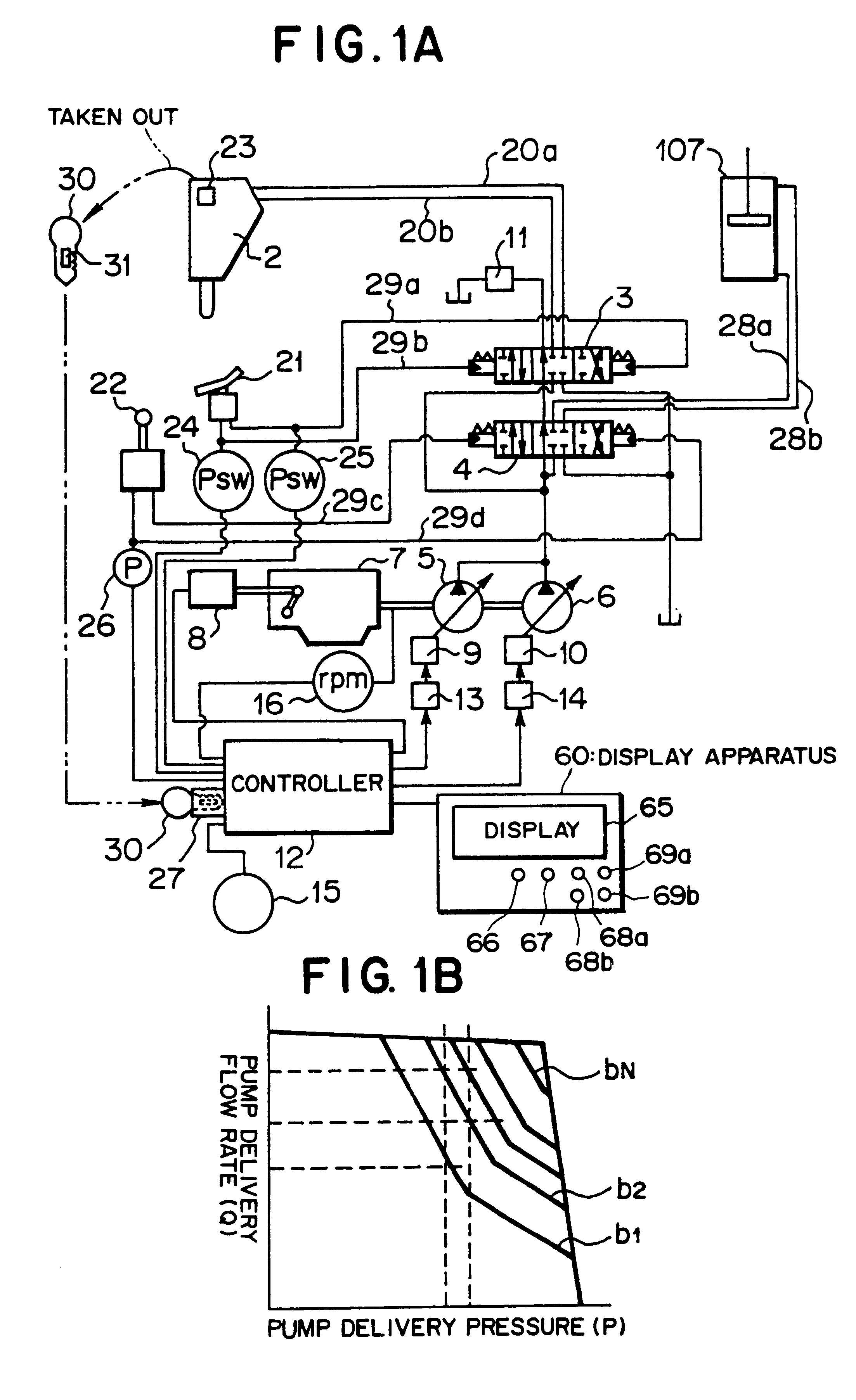
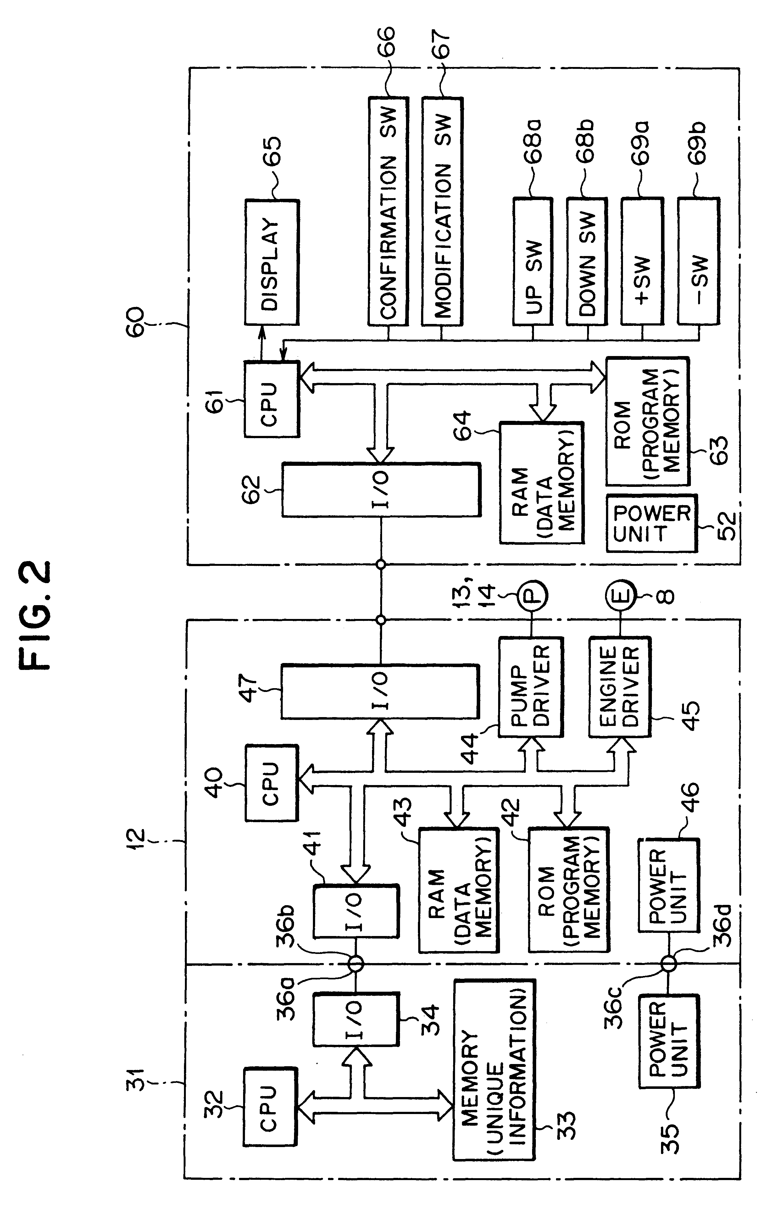
First, a control apparatus and a control method for a construction machine according to the present invention are described with reference to FIGS. 1A to 9.

Since the control apparatus for a construction machine according to the present embodiment is provided in a construction machine such as a hydraulic excavator, the construction machine such as a hydraulic excavator is described first.

In the construction machine 1 such as al hydraulic excavator, as described hereinabove in connection with the prior art (refer to FIG. 18), an upper revolving unit (construction machine body) 101 is mounted for revolving motion in a horizontal plane on a lower travelling body 100. The upper revolving unit 101 includes a main frame 102, and an operator cab 103, an engine room 104 and so forth provided on the main frame 102.

A boom 105 is connected for pivotal motion to the upper revolving unit 101 by a pin not shown, and a stick 106 is connected for pivotal motion to an end portion of the boom 105 by a...

second embodiment

(B) Description of the Second Embodiment

Subsequently, a control apparatus and a control method for a construction machine according to a second embodiment are described with reference to FIGS. 10 and 11. It is to be noted that, in FIGS. 10 and 11, like reference symbols to those of FIGS. 1A and 2 denote like members.

The control apparatus and the control method for a construction machine according to the present embodiment are different from those of the first embodiment in the uniform information storage member as shown in FIG. 10.

In particular, a male or female type connector 50A as a unique information storage member is removably provided in an attachment 2 according to the present embodiment. In particular, the attachment 2 has a female or male type connector 50B provided thereon, and the connector 50A is removably provided on the connector 50B'.

It is to be noted that the connector 50B' has a cover member 51 provided thereon so that the connector 50B' and the connector 50A may be...

third embodiment

(C) Description of the Third Embodiment

Subsequently, a control apparatus and a control method for a construction machine according to a third embodiment of the present invention are described with reference to FIGS. 12 and 13. It is to be noted that, in FIGS. 12 and 13, like reference symbols to those of FIGS. 1A and 2 denote like members.

The control apparatus and the control method for a construction machine according to the present embodiment are different in the unique information storage member from those of the first embodiment as shown in FIG. 12.

In particular, an attachment 2 according to the present embodiment has a bar code 70 provided thereon as a unique information storage member.

In the bar code 70, unique information for setting an operation condition required by the attachment 2 is stored as binary information. In particular, the bar code 70 usually includes a plurality of bars of black (hereinafter referred to as black bars) and bars of white (hereinafter referred to a...


PUM


Abstract

A control apparatus and a control method for a construction machine make it possible to set an operation condition suitable for the working attachment by a simple operation with certainty, even if unique information of a working attachment cannot be inputted. To this end, a control apparatus for a construction machine to which a working attachment is attached is constructed that includes a control section for controlling a hydraulic power source based on unique information about the working attachment, a display section which performs discrimination failure display when the type of the working attachment has not successfully been discriminated, and a standard set valve setting section for setting, when the discrimination failure display is performed by the display section, the type of the working attachment and a standard value regarding the operation condition of the working attachment, and that the control section is capable of controlling the hydraulic power source based on the operation condition set based on the unique information of the working attachment of information of the standard set valve set by the standard set valve setting section.

Description

This invention relates to a control apparatus and a control method for a construction machine such as a hydraulic excavator to which a plurality of working attachments such as, for example, a bucket and a breaker (hammer) can be attached, and more particularly to a control apparatus and a control method for a construction machine suitable for use with a construction machine wherein a type and so forth of an attachment attached to a construction machine body can be displayed.Conventionally, in a construction machine such as a hydraulic excavator which is a kind of working machine, various working attachments such as a breaker (hydraulic hammer) and a bucket can be removably attached comparatively readily so that the construction machine can perform various works.Here, a construction machine such as a hydraulic excavator to which a breaker 2 is attached as a working attachment is described with reference to FIG. 18.As shown in FIG. 18, in a construction machine 1 such as a hydraulic e...

Claims


Application Information

Patent Timeline
Patent Type & Authority Patents(United States)
IPC IPC(8): E02F9/20E02F9/22E02F9/26
CPCE02F9/2025E02F9/205E02F9/2235E02F9/26E02F9/2285E02F9/2292E02F9/2296E02F9/2282
Inventor MIKI, MASATOSHIHIKIYAMA, MITSURU
Owner CATEPILLAR SARL
Why Eureka
Try Eureka