
Keyboard switch assembly including actuator member with three active positions

a technology of keyboard switch and actuator, which is applied in the direction of electric switches, basic electric elements, electric apparatus, etc., can solve the problems of not providing a sealed closure of the opening, special and irksome operation, and difficult or even impossible to choose a button the same color as the other keys, and achieves high reliability of operation.

Inactive Publication Date: 2003-02-25
DRNC HLDG INC
View PDF12 Cites 90 Cited by
  • Summary
  • Abstract
  • Description
  • Claims
  • Application Information

AI Technical Summary

Benefits of technology

One object of the present invention is to alleviate the aforementioned drawbacks by proposing an actuator member of the type previously cited whose button and active component can be manufactured separately, necessitate no subsequent physical assembly, and are not connected by any physical connection, all this being achieved with guaranteed high reliability of operation and total discrimination between the various commands that can be given by means of said member.

Problems solved by technology

This has two major drawbacks: the visible parts of the members of all keypads are the same color, which sometimes does not match the other keys and / or the body of the keypad, and the button 102 is not centered or aligned optimally and reliably with the corresponding opening in the housing or envelope of the keypad and does not provide a sealed closure of the opening.
Also, the only possibility of misalignment is between the subassembly and the card, and therefore invisible to the user.
However, it is difficult or even impossible to choose a button the same color as the other keys, since the buttons and the keys are not generally produced by the same manufacturer.
What is more, this solution leads to a special and irksome operation of preassembling the subassembly and necessitates special physical connections between the housing of the keypad and the electronic circuit card.

Method used


Image

  • Keyboard switch assembly including actuator member with three active positions
  • Keyboard switch assembly including actuator member with three active positions
  • Keyboard switch assembly including actuator member with three active positions

Examples


Embodiment Construction

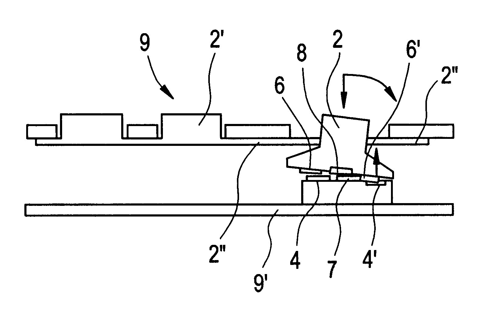
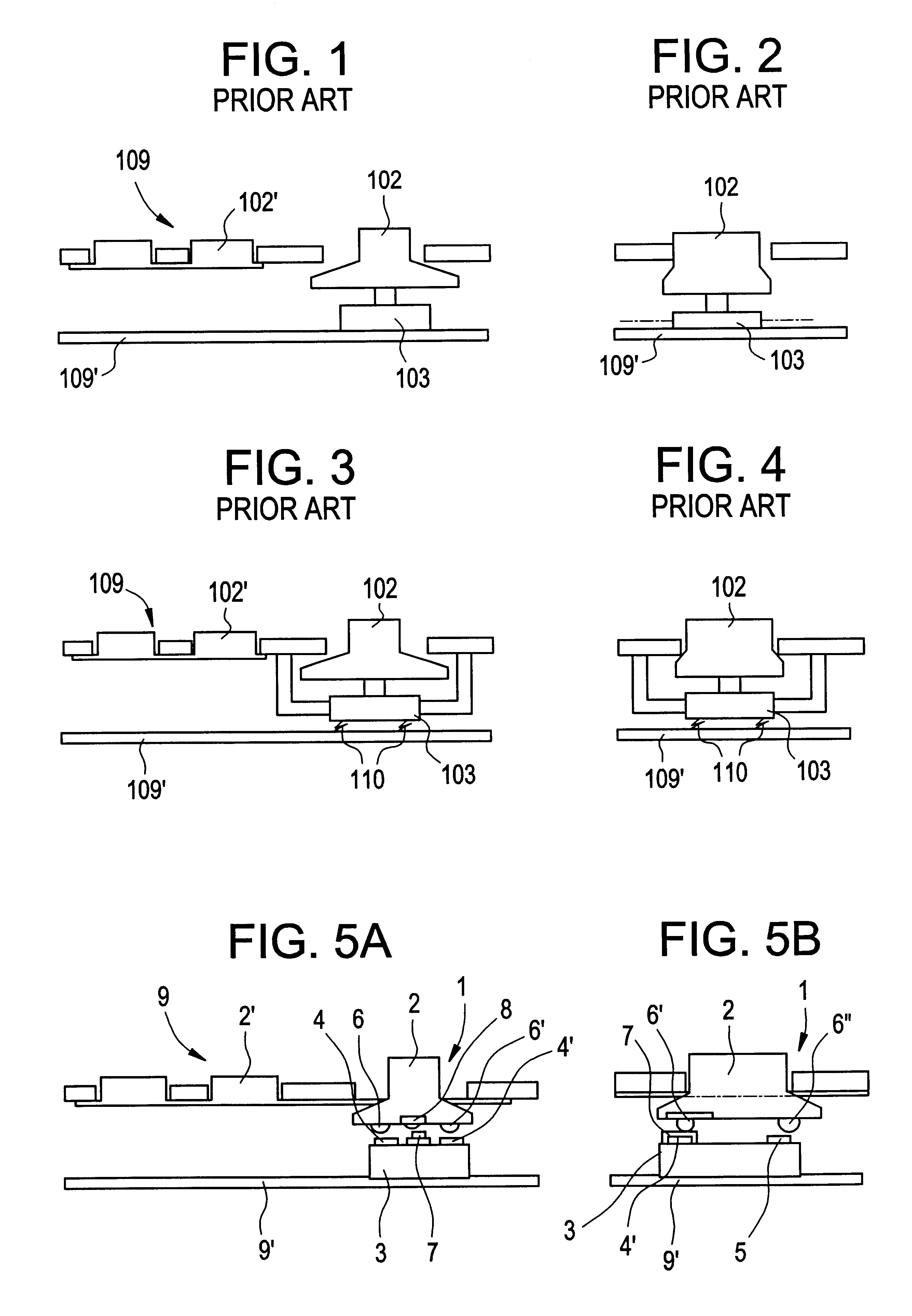
As shown in FIGS. 5 and 7 of the accompanying drawings, the actuator member 1 is of the multifunction key type, in particular of the navigation key type, and consists of a rigid button 2, mounted with limited mobility in translation and in rotation, and a separate detector component 3 comprising a plurality of pressure-sensitive active sites 4, 4' and 5, said button 2 having on its underside formations 6, 6' and 6" each intended to come into contact with one of the active sites 4, 4' and 5 of said component, as a function of the location, intensity and / or direction of pressure exerted by the user on the button 2.

In accordance with the invention, the detector component 3 of said member 1 has three active sites 4, 4', 5 disposed at the corners of a triangle, and between a first two of said sites 4, 4' there is a non-active bearing site 7 enabling, on its own or in conjunction with the third site 5, tilting of said button 2 by pivoting on said inactive site 7 towards one of said first ...


PUM


Abstract

The present invention provides an actuator member of the multifunction key type, in particular of the navigation key type, consisting of a rigid button mounted with limited mobility and a separate detector component having a plurality of active sites. The button has underside formations each intended to come into contact with one of the active sites. Three active sites are disposed at the corners of a triangle, wherein a non-active bearing site is disposed between two of the active sites, alone or in conjunction with the third active site, so as to allow tilting of the button by pivoting on the non-active site toward one of the first two active sites situated on respective sides thereof until the corresponding formation comes into contact with one of the active sites to activate it, for example by compressing it or depressing it.

Description

The present invention relates to actuator members for electronic instruments or devices, especially keys and keypads for data processing or telecommunications devices, and provides a navigator type actuator member and a device with a keypad including at least one such member.Such devices belong in particular to the following group: {fixed or mobile telephone; smart phone; personal digital assistant; desktop, portable or pocket computer; remote controller}.At present most multifunction key or navigation key actuator members take the form a pre-assembled sub-assembly mounted on an electronic circuit card 109' underlying the keys 102' of the keypad 109 of the device to ensure secure interconnection and cooperation of the button 102 and the detector active component 103 (see FIGS. 1 and 2).This has two major drawbacks: the visible parts of the members of all keypads are the same color, which sometimes does not match the other keys and / or the body of the keypad, and the button 102 is not...

Claims


Application Information

Patent Timeline
Patent Type & Authority Patents(United States)
IPC IPC(8): H01H25/04
CPCH01H25/041
Inventor VILLAIN, JEAN-CHRISTOPHECUPIF, BERTRANDBRISSON, LUC
Owner DRNC HLDG INC
Learn More