Hydrogen storage device and hydrogen storage system

a technology of hydrogen storage and hydrogen storage, which is applied in the direction of indirect heat exchangers, lighting and heating apparatus, furnaces, etc., can solve the problems of hydrogen occlusion alloy fatigue, long time-consuming heating of hydrogen occlusion alloy, and inability to achieve high energy efficiency

Inactive Publication Date: 2003-03-11
TOYOTA JIDOSHA KK
View PDF4 Cites 32 Cited by
  • Summary
  • Abstract
  • Description
  • Claims
  • Application Information

AI Technical Summary

Problems solved by technology

Hence, it takes a long time to heat the hydrogen occlusion alloy, and it is impossible to achieve high energy efficiency.
However, in the case where powder of a hydrogen occlusion alloy is used, the hydrogen occlusion alloy is fatigued by the repeated absorption and discharge of hydrogen and may become even finer.
This leads to a tendency for (pieces of) the hydrogen occlusion alloy that has become finer to scatter in the container and occupy a bottom portion of the container with high density (compaction).
In such a case, there is caused a problem of inconsistent density distribution of powder in the container, leading to localization of electric current paths.
This leads to a decrease in resistance of the bottom portion of the container and thus causes localization of the electric current paths in the bottom portion of the container.
Thus, there is caused a problem of difficulty in rapidly discharging hydrogen, especially when the hydrogen storage device is operating in cold conditions.
This leads to a problem of damage to the container, such as cracking.
Thus, there is caused a problem of difficulty in controlling a temperature of the hydrogen occlusion alloy through supply of electric current.
In the case of powder, since the hydrogen occlusion alloy is not constant in shape, it is difficult to constantly maintain physical contact between the electrode terminals and the hydrogen occlusion alloy.
Thus, under a circumstance where the internal resistance of a power source changes, the amount of heat generated by the hydrogen occlusion alloy is not always at its maximum.
Thus, in some cases, it is difficult to heat the hydrogen occlusion alloy within an extremely short period of time, and it is impossible to rapidly discharge hydrogen.

Method used


Image

  • Hydrogen storage device and hydrogen storage system
  • Hydrogen storage device and hydrogen storage system
  • Hydrogen storage device and hydrogen storage system

Examples


first embodiment

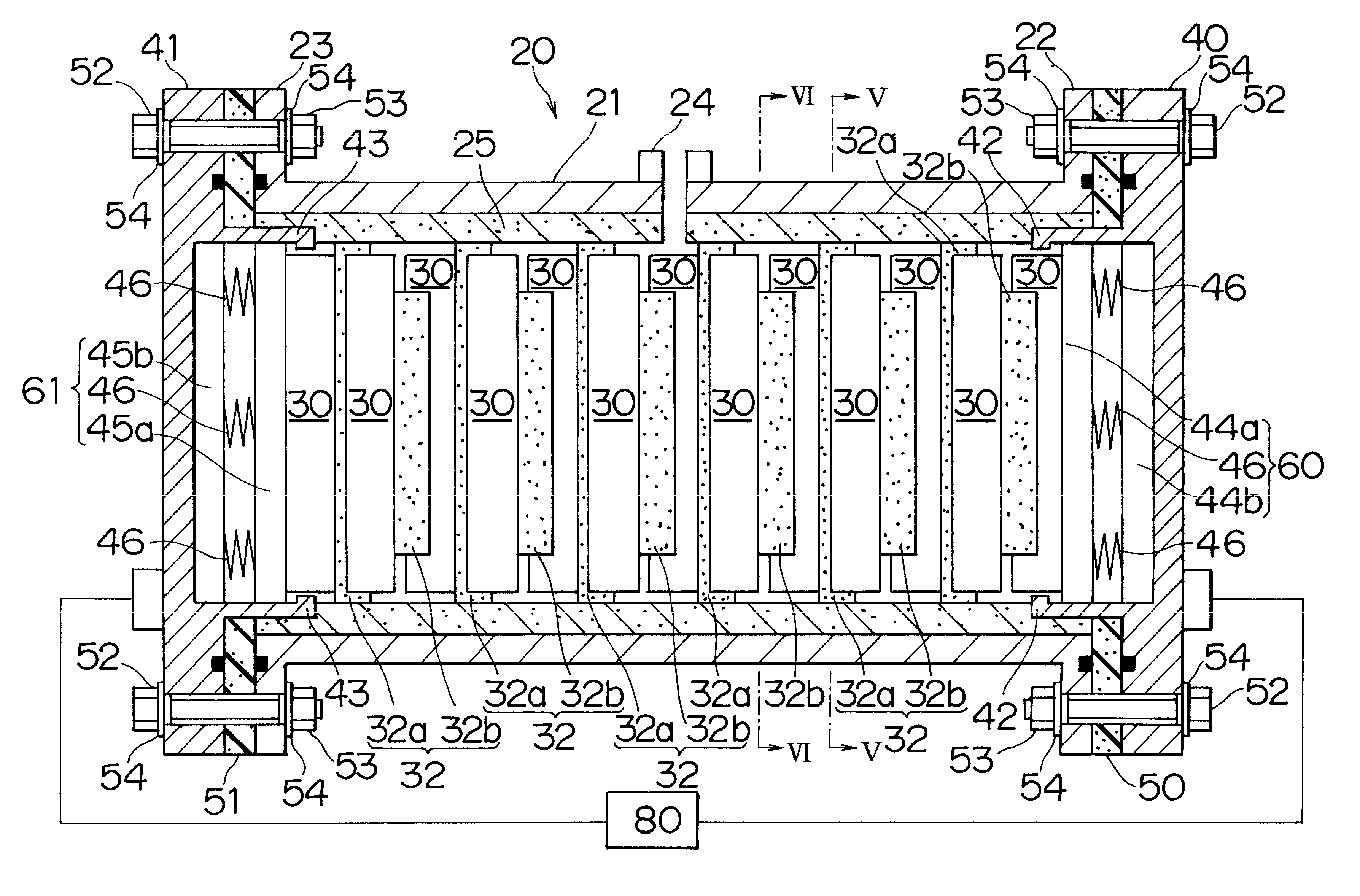
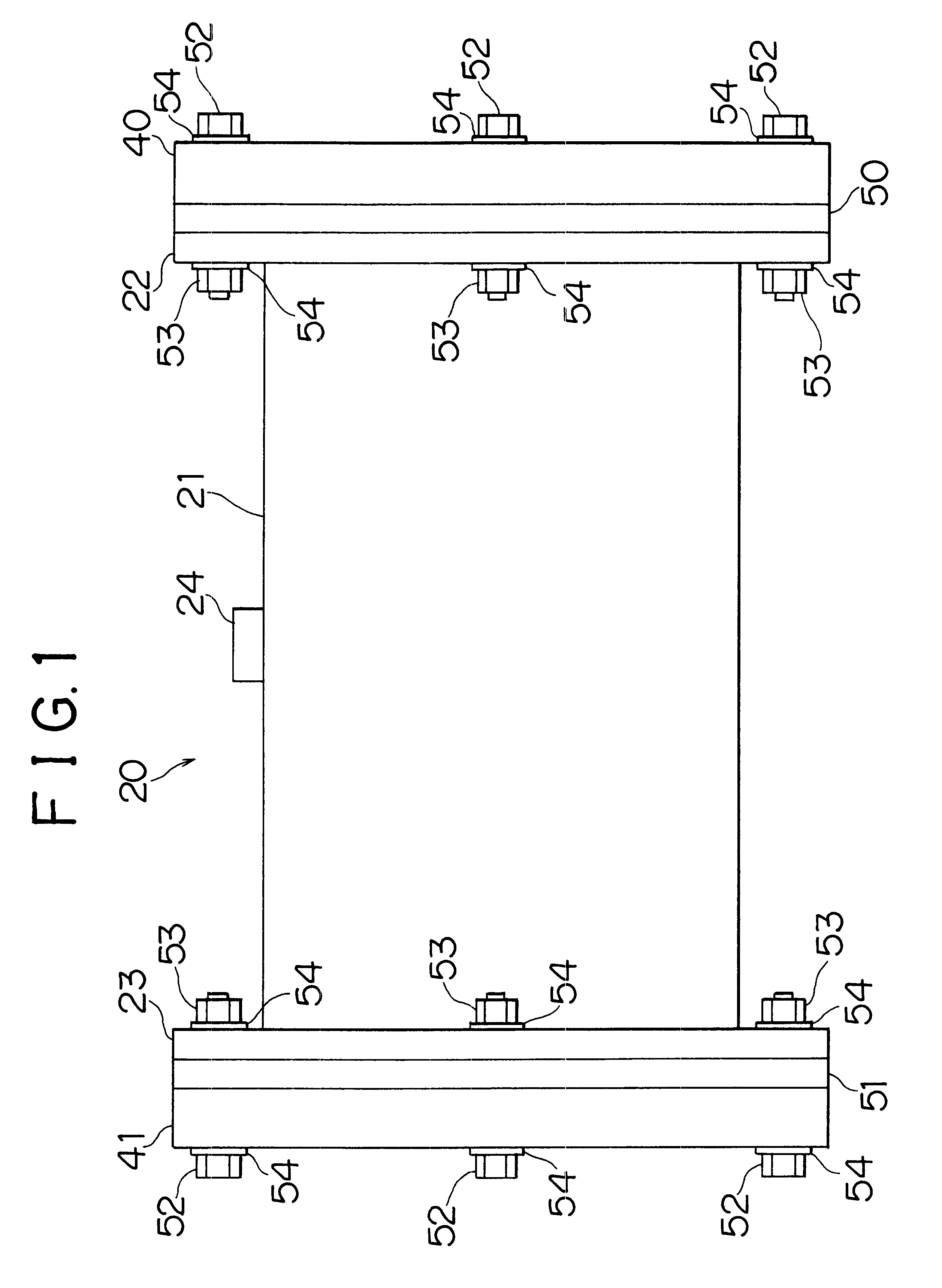
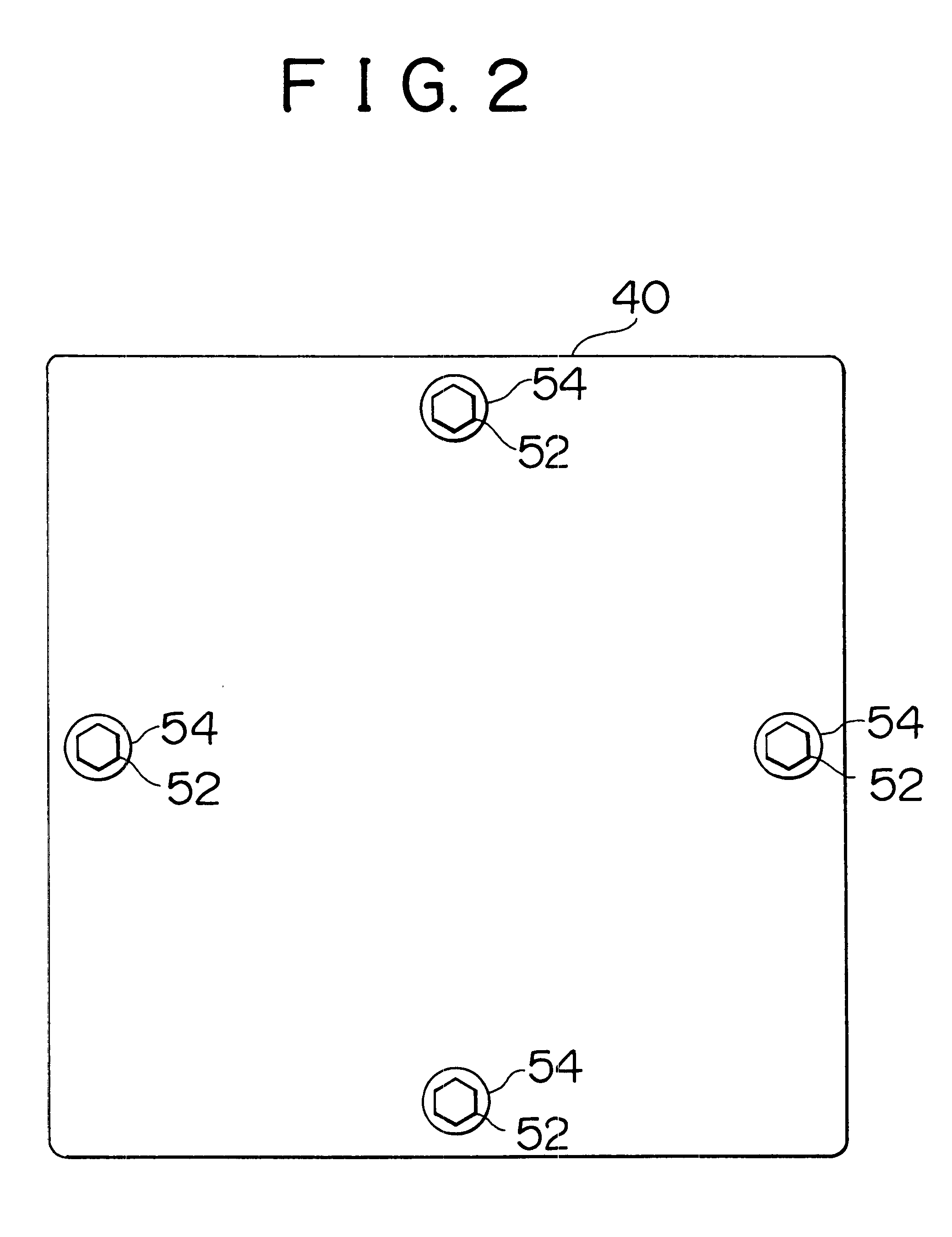
FIG. 1 is an exterior front view of a hydrogen storage device in accordance with the invention. FIG. 2 is a side view of the hydrogen storage device shown in FIG. 1. FIG. 3 is a longitudinal internal structural view of lids 40, 41 and a body 21 of the hydrogen storage device 20 shown in FIG. 1 when they are cut longitudinally.

The hydrogen storage device 20 is provided with the body 2, porous molded pieces 30 (see FIG. 3), and the lids 40, 41. The body 21 is made of a metal and has a cross-section of a rectangular tube. The porous molded pieces 30 are made of a hydrogen occlusion alloy and are disposed inside the body 21. The lids 40, 41 are made of a rectangular metal material and serve to close opposed end portions of the body 21. Flange portions 22, 23 are formed at the opposed end portions of the body 21, and a hydrogen inlet / outlet 24 is formed in an upper central portion of the body 21. Insulation gaskets 50, 51 (e.g., a non-porous ceramic material) are disposed between the lid...

second embodiment

Next, the invention will be described.

The second embodiment has the feature that a plurality of hydrogen storage devices 20 as described in the first embodiment are connected, and a connecting pattern of the hydrogen storage devices 20 is switched by a resistance control mechanism 82, whereby the internal resistance of hydrogen occlusion alloy in the hydrogen storage devices 20 is made to coincide with the internal resistance of the power source 80. In general, in order to heat hydrogen occlusion alloy (the molded pieces 30) in the hydrogen storage devices 20 within the shortest possible period of time, a maximum electric power needs to be supplied to the hydrogen occlusion alloy from the power source 80. A heat generation output P of hydrogen occlusion alloy in the equivalent circuit of the first embodiment shown in FIG. 8 is defined by the following equation (1).

P=IV=I.sup.2 R=V.sup.2 R / (r+R).sup.2 (1)

V is an electric voltage supplied by the power source 80,

I is an electric curren...

third embodiment

In the hydrogen storage device 100 in accordance with the third embodiment, a change in dimension of the molded piece 110 in the direction of the long axis resulting from its volume expansion at the time of occlusion of hydrogen is absorbed by the movable urging electrodes 60, 61, and a change in dimension of the molded piece 110 in the lateral direction is absorbed by the first and second conductive cushioning materials 120a, 120b. This prevents the molded piece 110 from directly contacting the adiabatic insulation material 25, cushions any impact on the molded piece 110, and prevents the molded piece 110 from being damaged. On the contrary, a change in dimension of the molded piece 110 in the direction of the long axis resulting from its volume reduction at the time of discharge of hydrogen is complemented by the movable urging electrodes 60, 61 urging and elongating the molded piece 110.

Thus, it is possible to maintain physical contact between opposed ends of the molded piece 110...


PUM

PropertyMeasurementUnit
thicknessaaaaaaaaaa
thicknessaaaaaaaaaa
thicknessaaaaaaaaaa

Abstract

A hydrogen storage device prevents localization of hydrogen occlusion alloy and ensures rapid discharge of hydrogen. The hydrogen storage device has a plurality of porous molded pieces arranged longitudinally at predetermined intervals. Conductive cushioning materials are inserted between the molded pieces and between the molded pieces and an adiabatic insulation material. The conductive cushioning materials include first conductive cushioning materials inserted between the adiabatic insulation material and upper and lower end surfaces of the molded pieces and second conductive cushioning materials inserted between left and right end surfaces of the adiabatic insulation material. Disposed at opposed ends of a row of the molded pieces are movable urging electrodes which can move in response to dimensional changes of the molded pieces resulting from their volume changes and which urge the molded pieces to constantly maintain physical contact between the molded pieces and lids.

Description

INCORPORATION BY REFERENCEThe disclosure of Japanese Patent Application No. HEI 11-247342 filed on Sep. 1, 1999 including the specification, drawings and abstract is incorporated herein by reference in its entirety.1. Field of the InventionThe invention relates to a hydrogen storage device and a hydrogen storage system employing a hydrogen occlusion alloy.2. Description of the Related ArtAs a general art for discharging hydrogen occluded by a hydrogen occlusion alloy, it is known to spread heat generated by a heating element over the entire hydrogen occlusion alloy by means of heat conduction. A total heat capacity in this art is the sum of a heat capacity of the heating element and a heat capacity of the hydrogen occlusion alloy. Thus, part of the energy applied to the hydrogen occlusion alloy for discharge of hydrogen is consumed to heat the heating element. Hence, it takes a long time to heat the hydrogen occlusion alloy, and it is impossible to achieve high energy efficiency.The...

Claims


Application Information

Patent Timeline
Patent Type & Authority Patents(United States)
IPC IPC(8): F17C11/00C01B3/00
CPCC01B3/0005F17C11/005Y02E60/327Y02E60/321Y02E60/32
Inventor NAKAMURA, KENJIMINOHARA, TAKETOSHI
Owner TOYOTA JIDOSHA KK
Why Eureka
Try Eureka