
Airblast fuel atomization system

a fuel atomization and air blast technology, which is applied in the ignition of turbine/propulsion engines, engine starters, lighting and heating apparatus, etc., can solve the problems of limiting the service life of the fuel injector, the inability to atomize fuel, and the difficulty of initiating the fuel ignition during engine startup cycles

Inactive Publication Date: 2003-04-01
DELAVAN +1
View PDF10 Cites 52 Cited by
  • Summary
  • Abstract
  • Description
  • Claims
  • Application Information

AI Technical Summary

Problems solved by technology

A common problem associated with industrial gas turbines is the difficulty associated with initiating fuel ignition during engine startup cycles.
However, at engine startup, when the engine is gradually spooling up, the fuel and / or air pressure needed to atomize the fuel is generally unavailable.
However, these small passages are susceptible to fuel contamination and carbon formation, and thus limit the service life of the fuel injector with which they are associated.
Typically, at ignition, airblast atomizers have difficulty atomizing heavy viscous industrial fuels, such as diesel fuel.

Method used


Image

  • Airblast fuel atomization system
  • Airblast fuel atomization system
  • Airblast fuel atomization system

Examples


Embodiment Construction

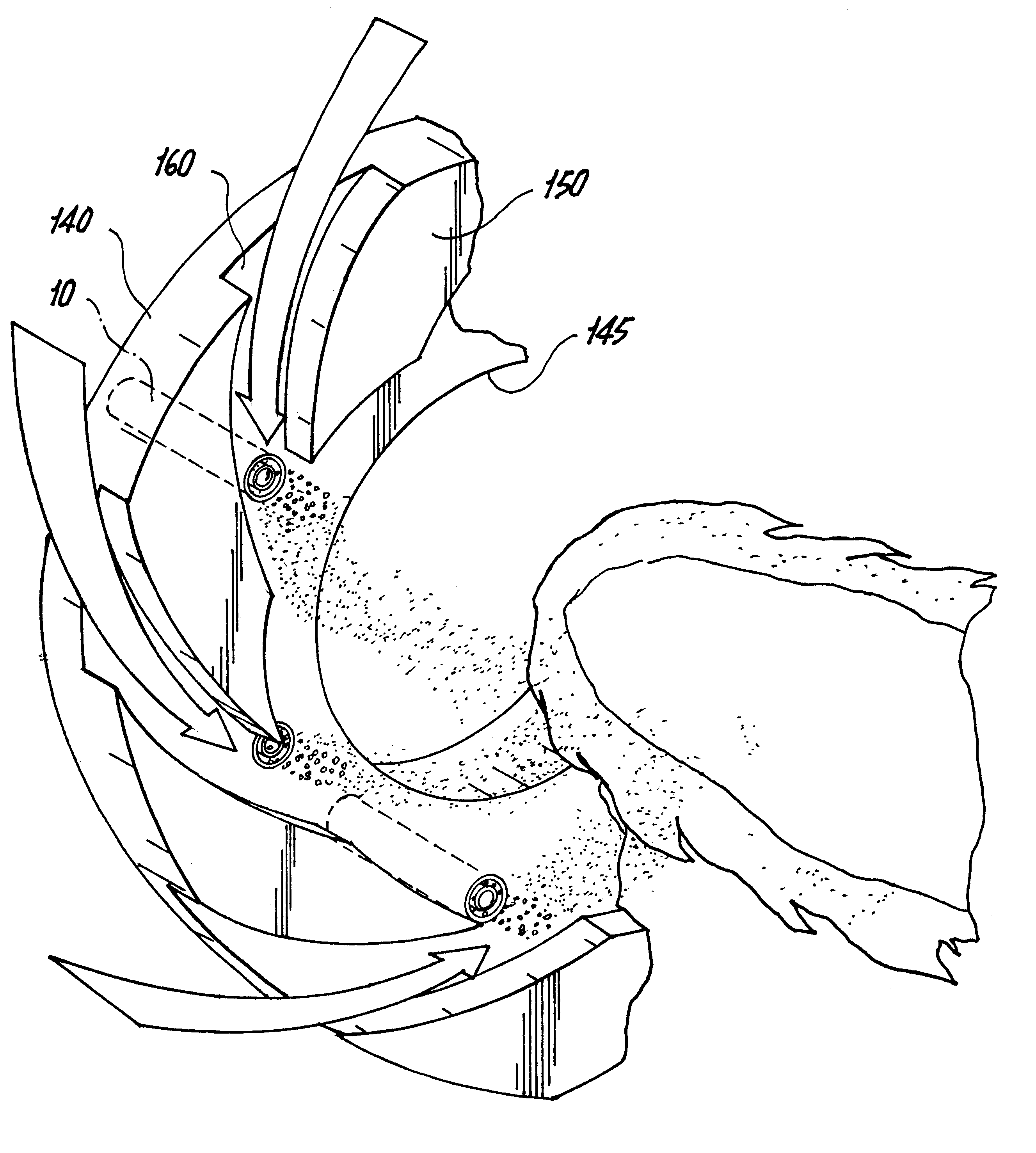
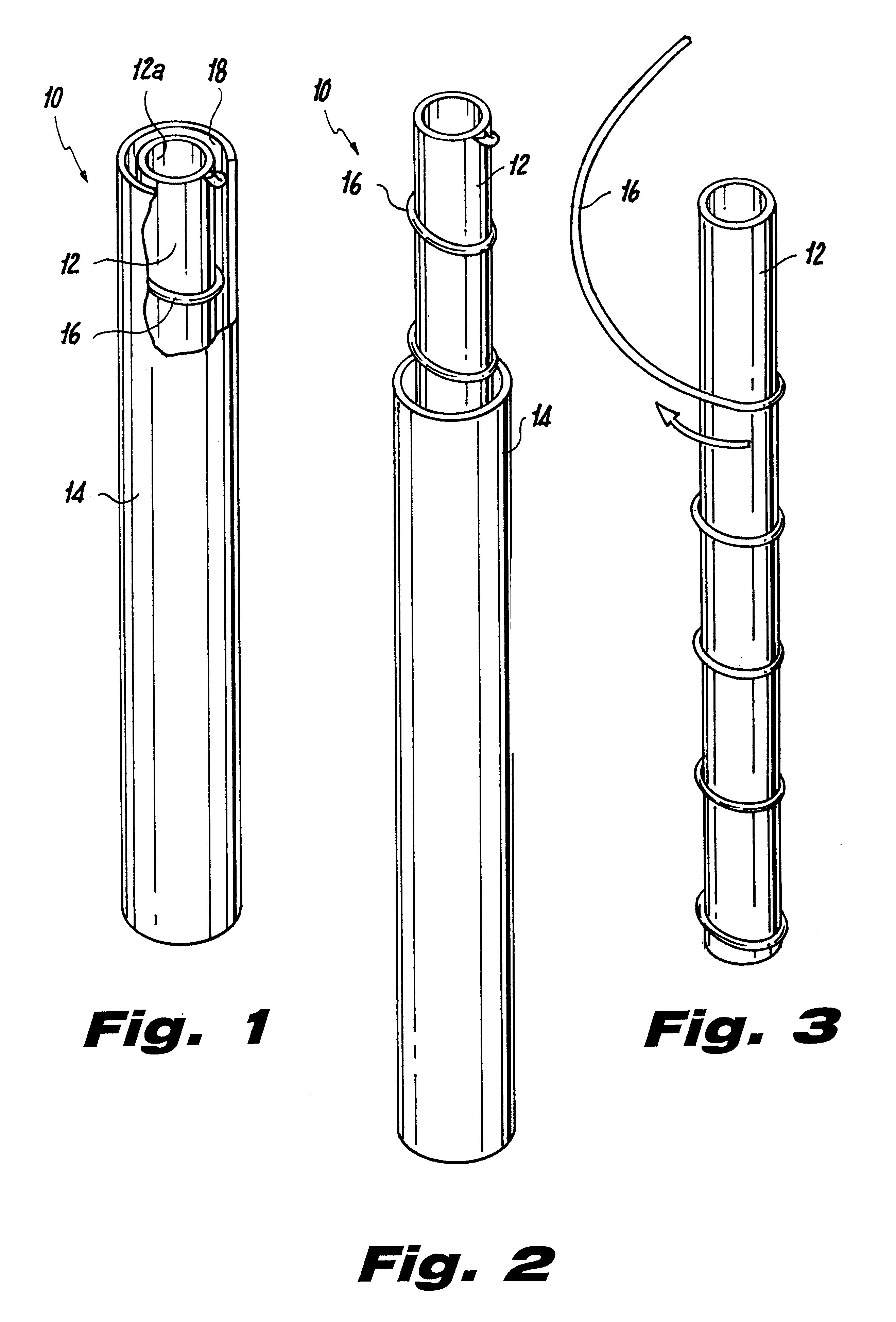
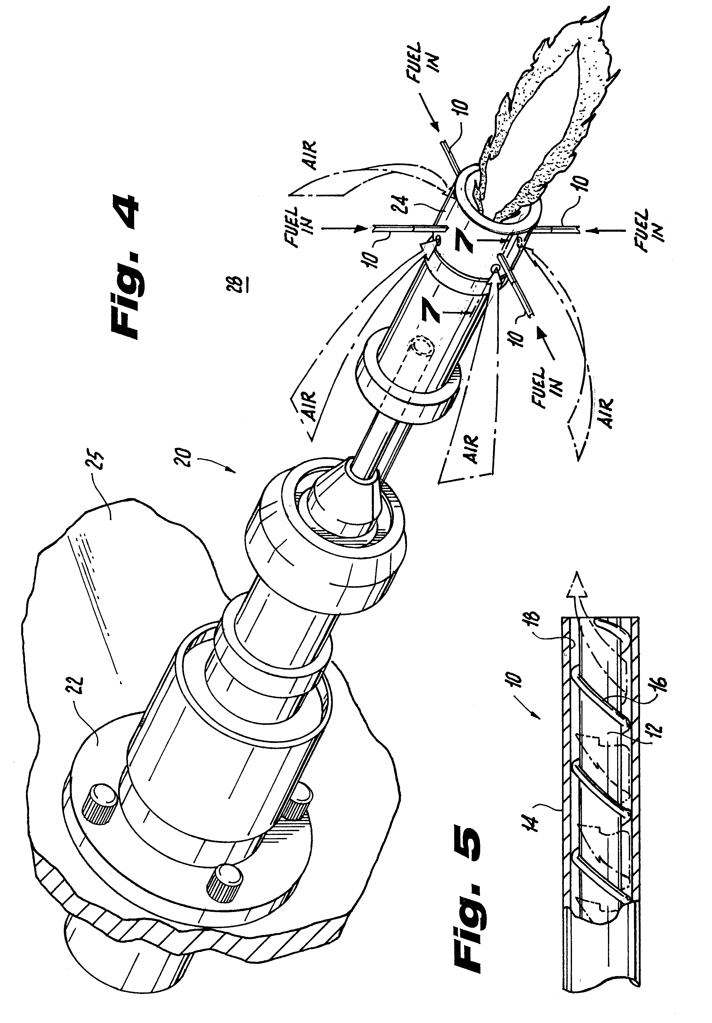
Referring now to the drawings wherein like reference numerals identify similar structural features of the apparatus disclosed herein, there is illustrated in FIG. 1 an airblast fuel injection device constructed in accordance with a preferred embodiment of the subject invention and designated generally by reference numeral 10. Fuel injection device 10 preferably includes concentric inner and outer tubular members 12 and 14. The tubular members are maintained in a coaxially spaced apart relationship by a helical spacer wire 16 wrapped around the inner tubular member 12, as illustrated in FIG. 3. Spacer wire 16 is preferably brazed onto the exterior surface of inner tubular member 12 and defines an annular fuel passage 18 between the inner and outer tubular members, which is best seen in FIG. 5.

The inner and outer tubular member 12 and 14 are not fastened together. This allows the outer tubular member 14 to move axially with respect to the inner tubular member 12, as shown for example ...


PUM


Abstract

An airblast fuel injector assembly for use in conjunction with a gas turbine is disclosed which includes an elongated tubular body having first and second concentric tubes separated from one another by a helical spacer wire so as to define a fuel passage therebetween. The injector assembly is situated such that fuel flow exiting the fuel passage is intersected by an air flow at a predetermined angle of incidence so as to atomize the fuel flow.

Description

1. Field of the InventionThe subject invention is directed to a fuel injection system for industrial gas turbines, and more particularly, to a fuel injection system for atomizing industrial grade fuels in gas turbines during ignition.2. Background of the Related ArtGas turbines are employed in a variety of industrial applications including electric power generation, pipeline transmission and marine transportation. A common problem associated with industrial gas turbines is the difficulty associated with initiating fuel ignition during engine startup cycles. Moreover, during startup, the fuel must be presented in a sufficiently atomized condition to initiate and support ignition. However, at engine startup, when the engine is gradually spooling up, the fuel and / or air pressure needed to atomize the fuel is generally unavailable.A broad range of fuel injection devices and methods have been developed to enhance fuel atomization during engine ignition sequences. One approach has been to...

Claims


Application Information

Patent Timeline
Patent Type & Authority Patents(United States)
IPC IPC(8): F23D11/10F23D11/38F23D11/36F23D11/00F23R3/28
CPCF23D11/383F23D11/107F23D11/103F05B2220/50
Inventor CORNWELL, MICHAEL DALENEWMAN, ANTHONY WILLIAMMILOSAVLJEVIC, VLADIMIR DUSAN
Owner DELAVAN
Learn More