Apparatus and method for friction stir welding using filler material

a technology of filler material and friction stir, which is applied in the direction of soldering apparatus, manufacturing tools,auxillary welding devices, etc., can solve the problems of geometric distortions near the weld joint of conventional welding processes, workpieces made of commercial metallic alloys (e.g., 2000- and 7000-series aluminum alloys) that are difficult to join by conventional welding processes,

Inactive Publication Date: 2003-04-08
LOCKHEED MARTIN CORP
View PDF22 Cites 116 Cited by
  • Summary
  • Abstract
  • Description
  • Claims
  • Application Information

AI Technical Summary

Problems solved by technology

Workpieces made of some commercial metallic alloys (e.g., most 2000- and 7000-series aluminum alloys) are difficult to join by conventional welding processes (e.g., arc welding processes).
Further, conventional welding processes can create geometric distortions near the weld joint due to high temperature gradients (non-uniform heating) induced in the workpiece during welding.
These distortions can cause warping and other dimensional defects in the workpiece, as well as residual stresses that can lead to premature failure by cracking in the weldment or HAZ (either due to static and / or fatigue stresses), lamellar tearing, or by stress-corrosion cracking in some metals.
In addition, some alloys and types of weld joints are difficult to join except in a flat position.
Further, traditional welding processes produce welding fumes, spatter, and a possibility of porosity in the deposited weld metal, due to entrained gases.
Thus, these oxide layers can readily become entrained in the weldment, causing defects that can decrease static and fatigue strength of the weldment.
The friction stir welding process has several limitations, however.
This requirement is due in large part to the fact that known friction stir welding processes do not employ the use of filler materials, which can be used to fill excessive gaps in weld joints.
Such stringent fit up requirements can result in higher workpiece preparation costs and workpiece fixturing costs.
These costs can escalate dramatically when large workpieces are joined.
Further, traditional friction stir welding processes can generally be used on only a limited number of joint types, e.g., butt joints and edge joints.
Joint types requiring a fillet, e.g., corner joints, lap joints, and filleted T-joints, cannot generally be accomplished using traditional friction stir welding processes, as filler metal is required to produce the fillet.

Method used


Image

  • Apparatus and method for friction stir welding using filler material
  • Apparatus and method for friction stir welding using filler material
  • Apparatus and method for friction stir welding using filler material

Examples


first embodiment

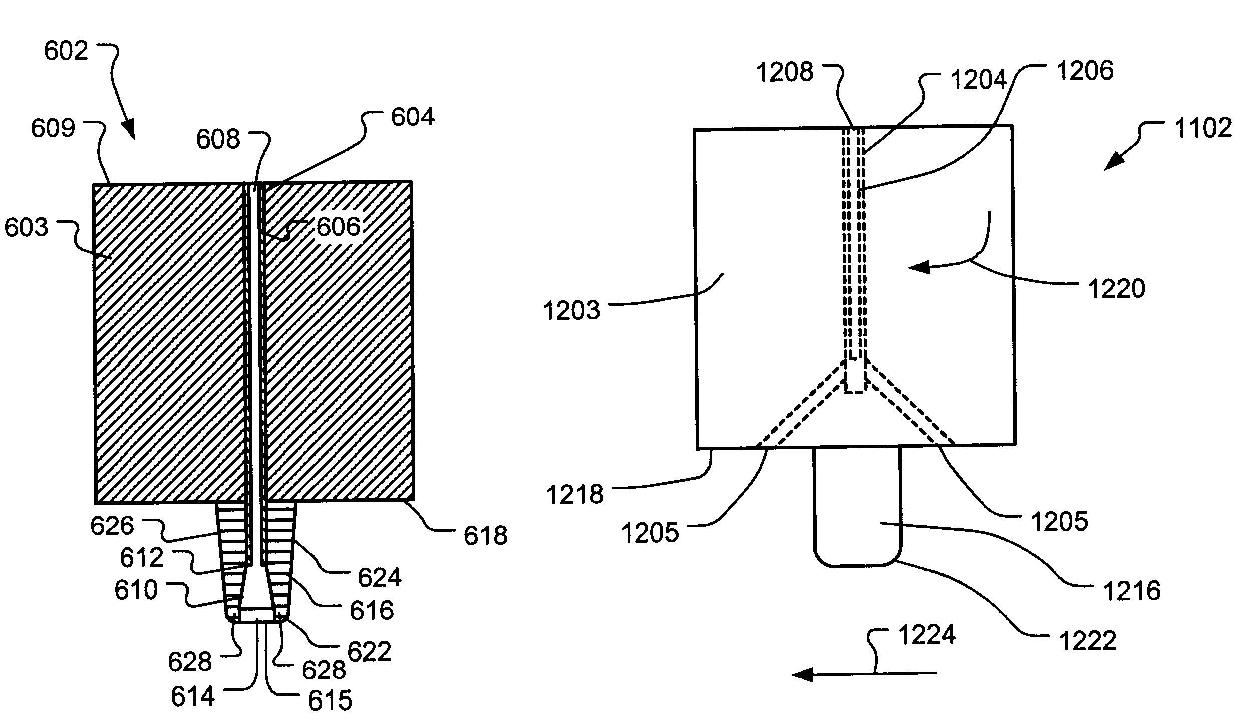
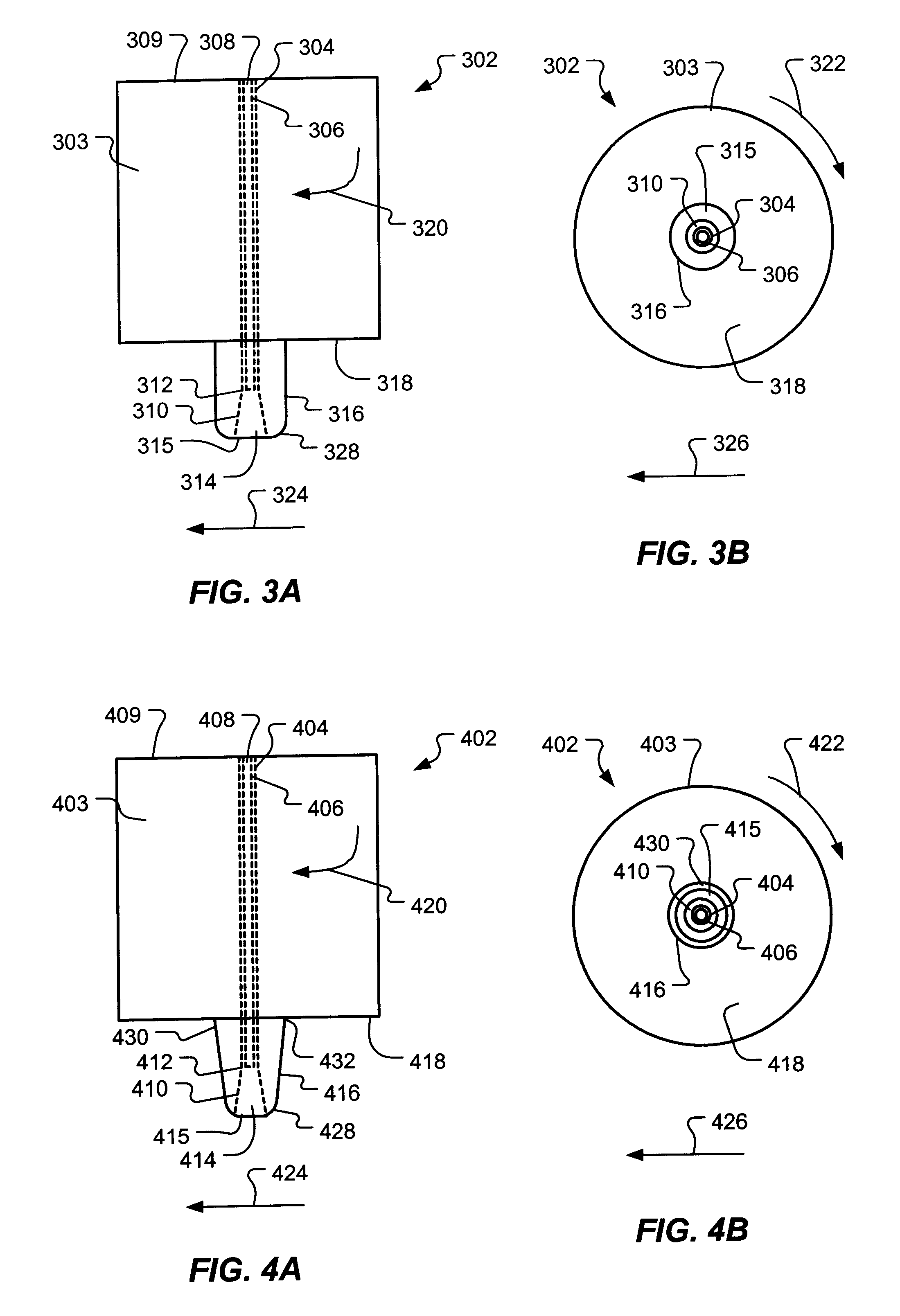
Referring now to FIGS. 3A and 3B, the friction stir welding tool 212 is shown. A friction stir welding tool 302 according to the present invention has a body 303 and a passageway 304 through the friction stir welding tool 302 capable of allowing a filler material (not shown) to pass therethrough. The passageway 304 further comprises an entrance opening 308 in an upper surface 309 of the body 303 and a flared portion 310 that transitions from a diameter at a transition location 312 along the passageway 304 to a larger diameter of an exit opening 314 in a lower surface 315 of a pin 316. While the illustrated embodiment provides the passageway 304 having the flared portion 310, it is within the scope of the present invention for the passageway 304 to have no flared portion, for the passageway 304 to taper from the entrance opening 308 to the exit opening 314, or for the flared portion 310 to begin at a location other than the transition location 312 along the passageway 304.

In one embo...

second embodiment

Referring now to FIGS. 4A and 4B, the friction stir welding tool 212 in FIG. 2 is shown. As compared to the embodiment of FIGS. 3A and 3B, the embodiment illustrated in FIGS. 4A and 4B includes a pin 416 that is tapered from an upper end 432 to a smaller diameter at a radiused portion 428.

A friction stir welding tool 402 according to the present invention has a body 403 and a passageway 404 through the friction stir welding tool 402 capable of allowing a filler material (not shown) to pass therethrough. The passageway 404 further comprises an entrance opening 408 in an upper surface 409 of the body 403 and a flared portion 410 that transitions from a diameter at a transition location 412 along the passageway 404 to a larger diameter of an exit opening 414 in a lower surface 415 of the pin 416. While the illustrated embodiment provides the passageway 404 having the flared portion 410, it is within the scope of the present invention for the passageway 404 to have no flared portion, fo...

third embodiment

the friction stir welding tool 212 shown in FIG. 2 is illustrated in FIGS. 5A and 5B. As compared to the embodiment of FIGS. 4A and 4B, the embodiment illustrated in FIGS. 5A and 5B includes a plurality of openings 528 leading from a flared portion 510 through a side surface 531 of a pin 516. A friction stir welding tool 502 comprises a body 503 and a passageway 504 through the friction stir welding tool 502 capable of allowing a filler material (not shown) to pass therethrough. The passageway 504 further comprises an entrance opening 508 in an upper surface 509 of the body 503 and the flared portion 510 that transitions from a diameter at a transition location 512 along the passageway 504 to a larger diameter of an exit opening 514 in a lower surface 515 of the pin 516. While the illustrated embodiment provides the passageway 504 having the flared portion 510, it is within the scope of the present invention for the passageway 504 to have no flared portion, for the passageway 504 to...


PUM

PropertyMeasurementUnit
thicknessesaaaaaaaaaa
frictionaaaaaaaaaa

Abstract

A friction stir welding tool includes a body having an upper surface defining an entrance opening and a lower surface, and a pin having a lower surface defining an exit opening, wherein the pin extends from the lower surface of the body. The friction stir welding tool further includes a passageway defined by the body and the pin from the entrance opening to the exit opening and is capable of allowing a filler material to pass therethrough. A friction stir welding method includes applying a frictional heating source to a workpiece to plasticize a volume of the workpiece and applying the frictional heating source to a filler material to plasticize the filler material. The method further includes introducing the filler material into the volume of the workpiece and incorporating the filler material into the volume of the workpiece.

Description

1. Field of the InventionThis invention relates to an apparatus and method for friction stir welding, and, in one aspect, to an apparatus and method for friction stir welding using filler material.2. Description of the Related ArtWorkpieces made of some commercial metallic alloys (e.g., most 2000- and 7000-series aluminum alloys) are difficult to join by conventional welding processes (e.g., arc welding processes). For example, 2000-series aluminum alloys are sensitive in heat-affected zones (HAZs) where the base metal reaches temperatures between liquidus and solidus during welding. In this area, partial melting at grain boundaries forms a network containing brittle intermetallic compounds of CuAl.sub.2. Thus, weld ductility can be substantially reduced. Further, conventional welding processes can create geometric distortions near the weld joint due to high temperature gradients (non-uniform heating) induced in the workpiece during welding. These distortions can cause warping and o...

Claims


Application Information

Patent Timeline
Patent Type & Authority Patents(United States)
IPC IPC(8): B23K20/12
CPCB23K20/128B23K20/1255
Inventor HATTEN, TIMOTHY E.ARBEGAST, WILLIAM J.
Owner LOCKHEED MARTIN CORP
Why Eureka
Try Eureka