Traverse linearity compensation method and rotational accuracy compensation method of measuring device

a compensation method and measurement device technology, applied in measurement devices, speed/acceleration/shock measurement devices, test/calibration, etc., can solve problems such as difficulty in correctly setting workpieces during measurement, affecting the accuracy of measurement, and requiring skill

a compensation method and measurement device technology, applied in measurement devices, speed/acceleration/shock measurement devices, test/calibration, etc., can solve problems such as difficulty in correctly setting workpieces during measurement, affecting the accuracy of measurement, and requiring skill

US6546640B2Inactive Publication Date: 2003-04-15MITUTOYO CORP

Image

  • Traverse linearity compensation method and rotational accuracy compensation method of measuring device
  • Traverse linearity compensation method and rotational accuracy compensation method of measuring device
  • Traverse linearity compensation method and rotational accuracy compensation method of measuring device

Examples


first embodiment

[Modification of First Embodiment]

Incidentally, though the master workpiece MW or the workpiece W is directly rested on the rotary table 3 for measurement in the above-described first embodiment, the master workpiece MW may be rested on the rotary table 3 through a measurement jig 11 as shown in FIG. 8.

The measurement jig 11 has a mount 12. The mount 12 is half-cylinder formed by cutting a short cylinder in half at the center thereof and has a workpiece mounting surface 13 on an upper surface thereof, a reference ball 15 being half-buried at the center of the cut vertical reference surface 14. The master workpiece MW is fixed on the workpiece mounting surface 13 by wringing.

In measuring the master workpiece MW, the master workpiece MW is initially rested on the workpiece mounting surface 13 of the mount 12 so that one side (measurement surface) of the master workpiece MW coincides with the vertical reference surface 14. Thereafter, the probe 7A of the sensor 7 is brought into contac...

second embodiment

[Second Embodiment]

FIGS. 10 to 13 show a second embodiment of the present invention.

The present embodiment is an application of the present invention to a rotational accuracy compensation method of a roundness measuring device.

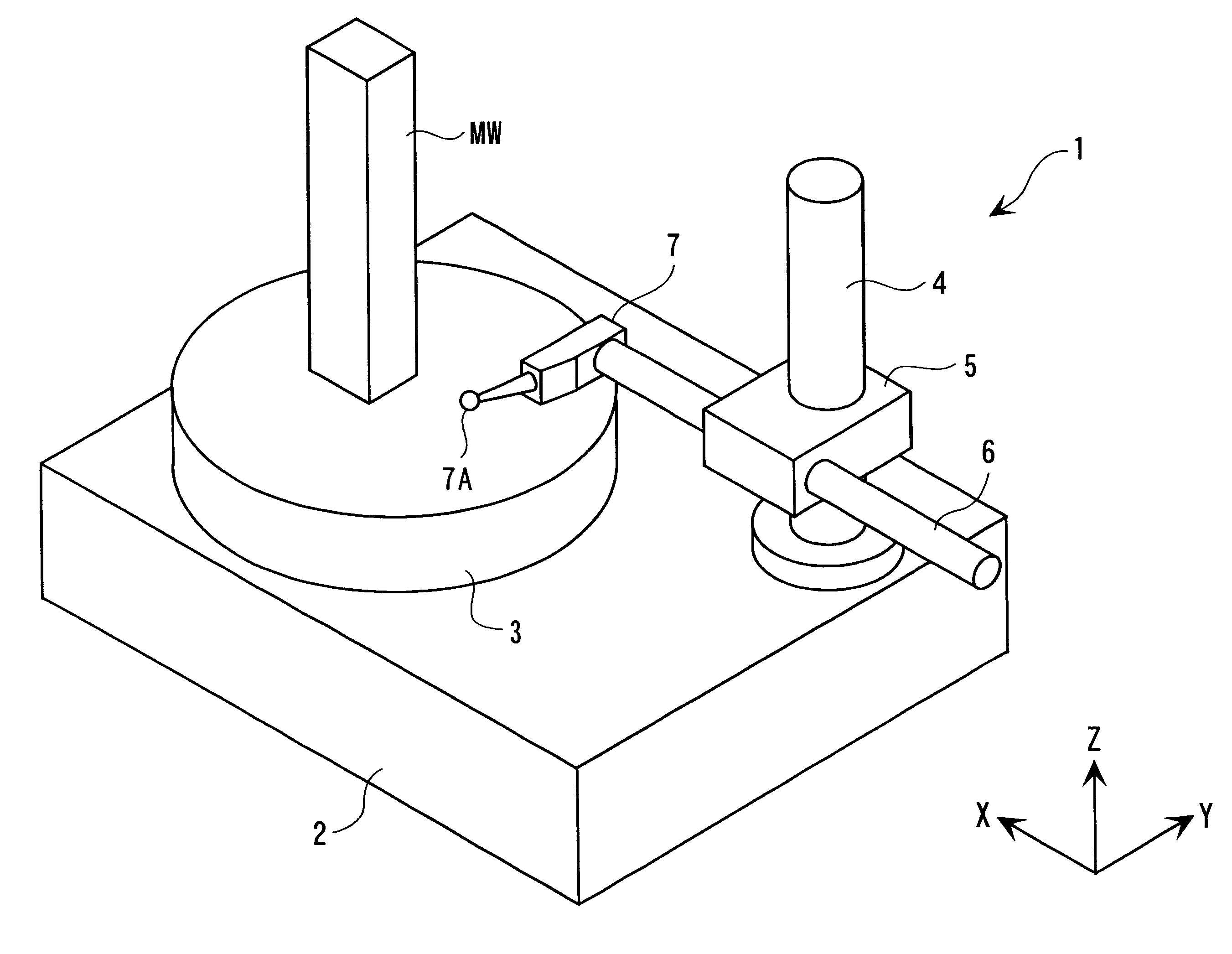
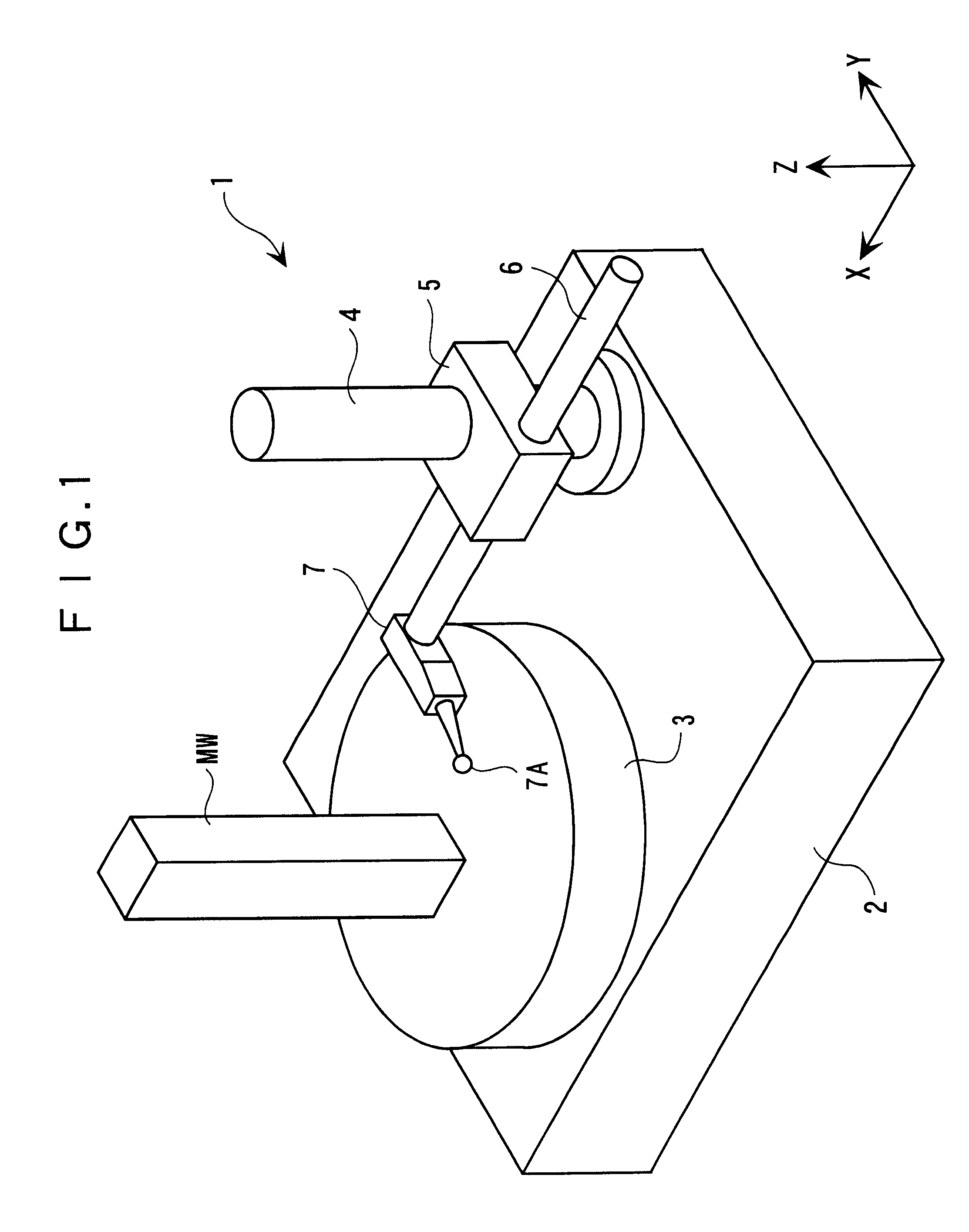
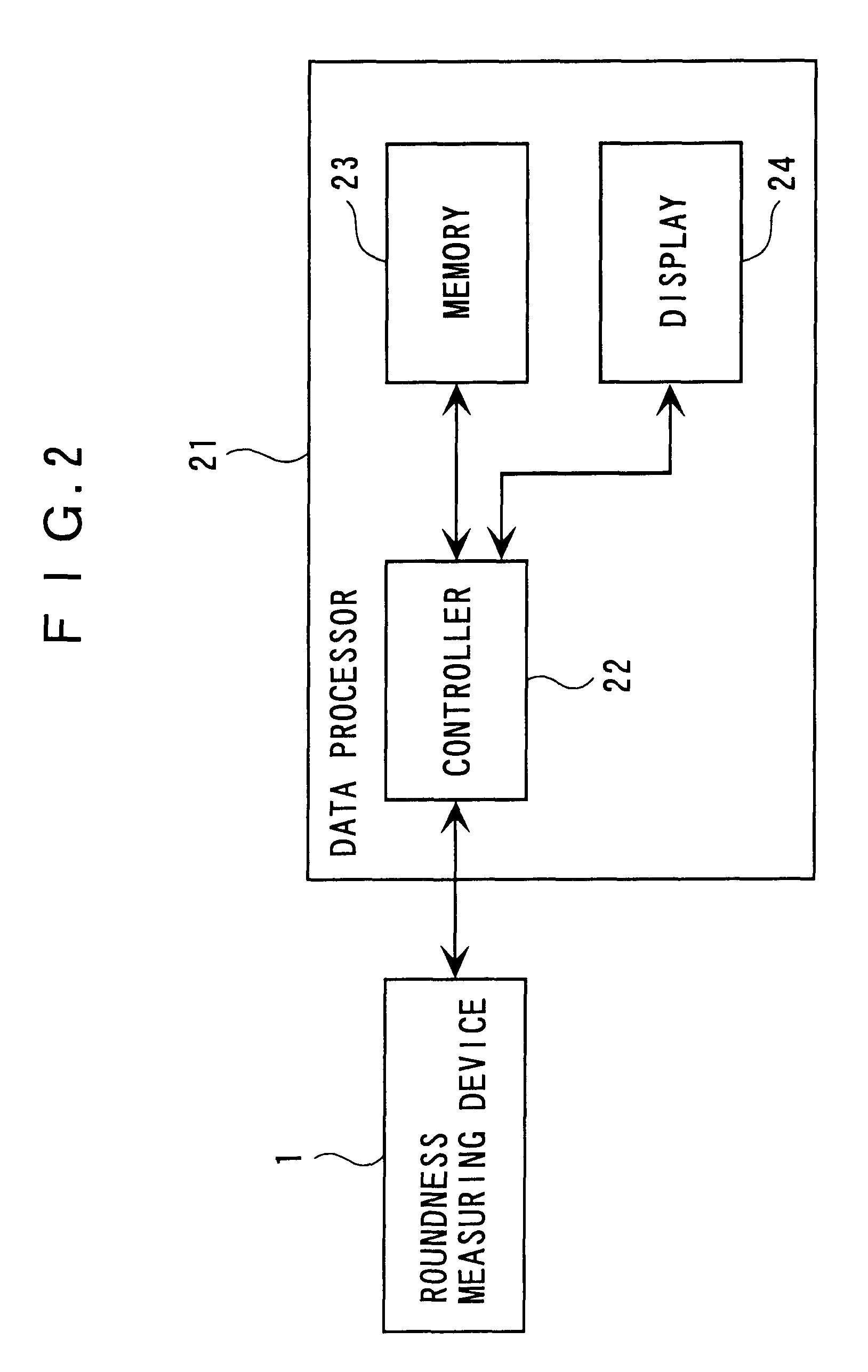
FIG. 10 shows a roundness measuring device 1 according to the present embodiment. The roundness measuring device 1 is the same as the roundness measuring device 1 of the above-described first embodiment and detailed explanation of specific components is omitted herein.

In the present embodiment, a workpiece (not shown) is put on the rotary table 3 and the master workpiece MW is rested through a measurement jig 11.

The measurement jig 11 has a short-cylindrical mount 12 having a master workpiece MW on an upper surface 13 thereof, and a reference ball 15 buried and half-exposed on the periphery of the mount 12. The outer diameter of the mount 12 and the master workpiece MW are concentric. The master workpiece MW is formed in a hemisphere of which profile data acqu...


PUM


Abstract

A compensation method according to the present invention includes: a traverse linearity data calculating step for measuring a master workpiece (MW) of which profile data is value-specified in advance while moving a sensor (7) using a linear movement mechanism (4, 5) of a measuring device (1) and for subtracting the previously value-specified profile data from the measurement data of the master workpiece to obtain a traverse linearity data of the linear movement mechanism; a workpiece measurement data calculating step for measuring the workpiece while moving the sensor by the linear movement mechanism of the measuring device to obtain a measurement data of the workpiece; and a workpiece profile calculating step for subtracting the traverse linearity data from the workpiece measurement data to obtain a true value data of the workpiece.

Description

1. Field of the InventionThe present invention relates to a traverse linearity compensation method and a rotational accuracy compensation method of a measuring device. More specifically, it relates to a traverse linearity compensation method of a measuring device having a linear movement mechanism, such as a roundness-measuring device and a roughness-measuring device, for compensating traverse linearity of the linear movement mechanism. It also relates to a rotational accuracy compensation method of a measuring device having a rotary mechanism such as a roundness-measuring device for compensating a rotational accuracy of the rotation mechanism.2. Description of Related ArtWhen a workpiece is measured by a measuring device having a linear movement mechanism as a guide (reference) such as a roundness-measuring device and a roughness-measuring device, the resulted measurement data is a composition of a profile data of the workpiece and a mechanical accuracy of the linear movement mecha...

Claims


Application Information

Patent Timeline
15 Apr 2003
Publication
US6546640B2
IPC
G01B5/008
CPC
G01B5/008; G01B21/042; G01B21/045; G01B5/201
Inventors
OKADA, EIJI; OMORI, YOSHIYUKI