Systems and methods for detecting fault conditions and detecting and preventing potentially dangerous conditions in an optical system

a technology of optical system and fault condition, applied in the field of optical fiber system, can solve problems such as irreparable damage to the connector, connector replacement, and danger, and achieve the effect of preventing the damage of the connector and detecting the fault condition

Inactive Publication Date: 2003-04-15
CIENA
View PDF3 Cites 63 Cited by
  • Summary
  • Abstract
  • Description
  • Claims
  • Application Information

AI Technical Summary

Benefits of technology

In yet another implementation in which a plurality of optical pump sources are utilized to amplify the signal, the invention may detect a backreflection from one optical pump source and control all of the optical pump sources to reduce power or shut down.

Problems solved by technology

This is particularly true of distributed amplifiers such as Raman amplifiers which may use such high power densities (e.g. 5 MW / cm.sup.2) that dangerous conditions exist when the pumping light escapes the optical system or when imperfect connections exist.
Imperfect connections may be caused, for example, by imperfect mating of fibers or by surface contamination on the fiber ends (e.g. oils, dust, or dirt) that can absorb some of the optical pump power and cause a hot spot, which could irreparably damage the connector.
Once damaged, the connector must be replaced.
Indeed, the high power density used by many optical pump lasers may exceed governmental safety standards.
If the fiber or an optical component connected to the fiber is damaged in some way such as by cutting or breaking or if somebody disconnects a component downstream of the optical pump, then the pumping light may escape the optical system and thereby create a hazardous condition for humans.
These hazardous conditions include not only risks of eye damage but also skin and perhaps even other bodily damage.
A disconnected fiber end or a damaged fiber may also cause high power density pumping light to impinge on other optical components and cause damage.
If the optical fiber is damaged or if a connection or component in the optical system is degraded or failed, then these conditions cause pumping light to be reflected.

Method used


Image

  • Systems and methods for detecting fault conditions and detecting and preventing potentially dangerous conditions in an optical system
  • Systems and methods for detecting fault conditions and detecting and preventing potentially dangerous conditions in an optical system
  • Systems and methods for detecting fault conditions and detecting and preventing potentially dangerous conditions in an optical system

Examples


first embodiment

Exemplary Operation (First Embodiment)

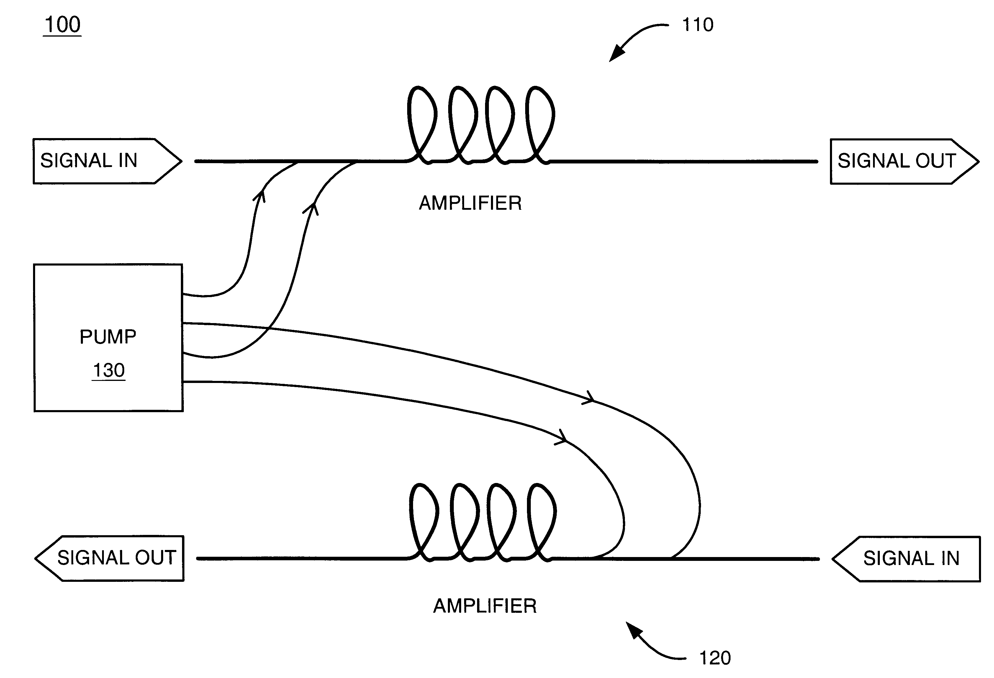
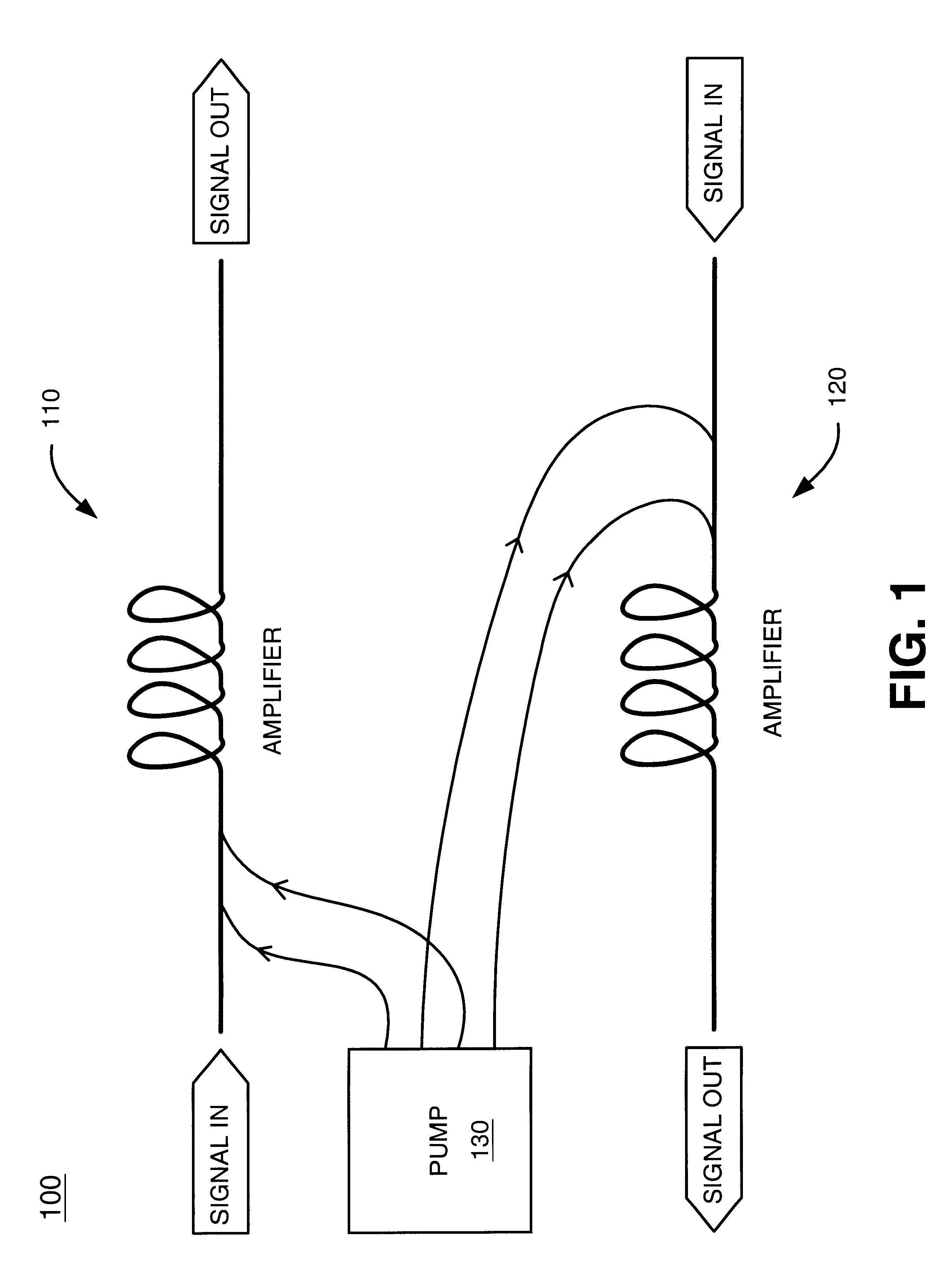
FIG. 5 is a flowchart of exemplary processing for detecting an imperfect connection in a manner consistent with the present invention. Processing begins when the laser 310 (FIG. 3) begins to power up [step 510]. At this time, the laser 310 emits a light signal of low power. Over time, the laser 310 ramps up to emit a light signal of high power, such as 100-500 mW.

As the laser 310 ramps up, it transmits the light signal to the coupler 350 via the pump fiber 320A. Assume that the coupler 350 has a 1 percent tap. The coupler 350 transmits 99 percent of the received signal to the connector 330 over pump fiber 320B and the remaining 1 percent of the signal on the terminated fiber 342 [step 520]. If the connection provided by the connector 330 is imperfect through, for example, an imperfect mating of fibers or surface contamination on the fiber ends, a portion of the signal transmitted on the pump fiber 320B reflects back from the connector 330 [step ...

second embodiment

Exemplary Operation (Second Embodiment)

In general, the second embodiment operates as follows. The backreflection detector 770 receives any backreflections of the pumping light signal. Such backreflections of the pumping light signal may be generated by such things as a degraded or failed (imperfect) connector / component 750 or fiber 795. As described above a connector / component 750 may be degraded by a variety of factors such as contamination. Fibers may be damaged in a variety of ways such as by cutting. In addition, disconnecting a connector or fiber from a component in the system will cause backreflections of the pumping light signal and create a condition potentially hazardous to humans or components.

The invention detects these pumping light backreflections by utilizing the backreflection detector 770. The signal from backreflection detector 770 is fed to controller 790 which then utilizes this signal to determine whether the backreflection is significant enough to warrant precau...


PUM


Abstract

A system detects potentially dangerous conditions, prevents damage to optical components, and prevents humans from being physically harmed by stray pumping light. Optical systems employing distributed amplification such as Raman amplification utilize pumps having high output powers. These high output powers create dangerously high power densities in the optical fiber. If a connection is imperfect a hot spot may develop and the connection damaged by the pumping light. Fiber damage, disconnections and component degradations or failures may also permit the pumping light to escape the intended path and cause physical harm to humans as well as equipment. Pumping light backreflections caused by such imperfect connections, degraded / failed components, and fiber damage are detected. A controller compares the backreflection amount against a threshold to determine whether a precautionary measure should be taken such as shutting down the pump, decreasing pump power to a safe level or setting a maintenance flag. Multiple thresholds may be utilized to distinguish between different conditions such as degraded and failed conditions and to exercise appropriate levels of precautionary measure(s). The detection of distributed pumping light backreflections may also be used to shut or power down other types of pumps such as an EDFA.

Description

1. Field of the InventionThe present invention relates generally to optical fiber systems and, more particularly, to systems and methods that detect a potentially dangerous condition in an optical system and take precautionary measures to reduce or eliminate the potentially dangerous condition. The present invention also relates to systems and methods that detect signal and pump path integrity.2. Description of Related ArtOptical communication systems have replaced other communication mediums due to their many advantages. For example, optical communication systems typically have wide bandwidth and low attenuation, are immune to electrical noise, offer relatively secure transmission of signals, and can transmit signals over long distances.Despite the low attenuation of optical communication systems, the optical signals they transmit nevertheless require amplification. Although many types of optical amplifiers currently exist, the most widely used amplifiers are lumped or discrete amp...

Claims


Application Information

Patent Timeline
Patent Type & Authority Patents(United States)
IPC IPC(8): H04B10/08
CPCH04B10/071
Inventor STUMMER, ALAN D.FRIEDRICH, LARS
Owner CIENA
Why Eureka
Try Eureka