Universal workholding V fixture convertable to other applications

a technology of v fixture and workholding device, which is applied in the direction of clamps, manufacturing tools, and surfaces, can solve the problems of less access to cutting tools, clamps that do not allow the block to be held on the clamping side, and interfere with machining operations, so as to facilitate machining and minimize tool interference. , the effect of low profil

Inactive Publication Date: 2003-04-29
ANDRONICA RANDALL C
View PDF14 Cites 54 Cited by
  • Summary
  • Abstract
  • Description
  • Claims
  • Application Information

AI Technical Summary

Benefits of technology

It is therefore an object of the current invention to provide a workholding V fixture that can hold round, square, hexagonal, rectangular, threaded, or irregular parts. It is an object of the current invention to provide a workholding device that can hold multiple workpieces. It is another object of the invention to hold a workpiece securely for machining. Another object is to provide a non-marring grip. It is yet another object to provide a workholding device that can be held on any side for machining. A further object is to provide a low profile so as to facilitate machining by minimizing tool interference. It is still a further object to provide a versatile device capable of holding workpieces to replicate itself and its accessories, and further that can be adapted to accomplish a range of tasks beyond merely workholding which include punching parts, dressing diamond wheels, sharpening very small and very large drills, performing deep hole center drilling, generating radii on a part and centerless grinding workpieces. And another objective is to extend the clamping and linear motion concepts of the invention to replacing the screw quill arrangement on the tailstock of a lathe.

Problems solved by technology

Additionlly, the clamp has a high profile which may interfere with machining operations.
Furthermore, small diameter workpieces are located at the bottom of the V making it less accessible to a cutting tool.
And, the clamp will not allow the block to be held on the clamping side.
While the workpiece may be drilled in more than one plane it is rather a cumbersome fixture geared to production drilling of parts and it could not be inverted or held in a vise for use on various machines.

Method used


Image

  • Universal workholding V fixture convertable to other applications
  • Universal workholding V fixture convertable to other applications
  • Universal workholding V fixture convertable to other applications

Examples


Embodiment Construction

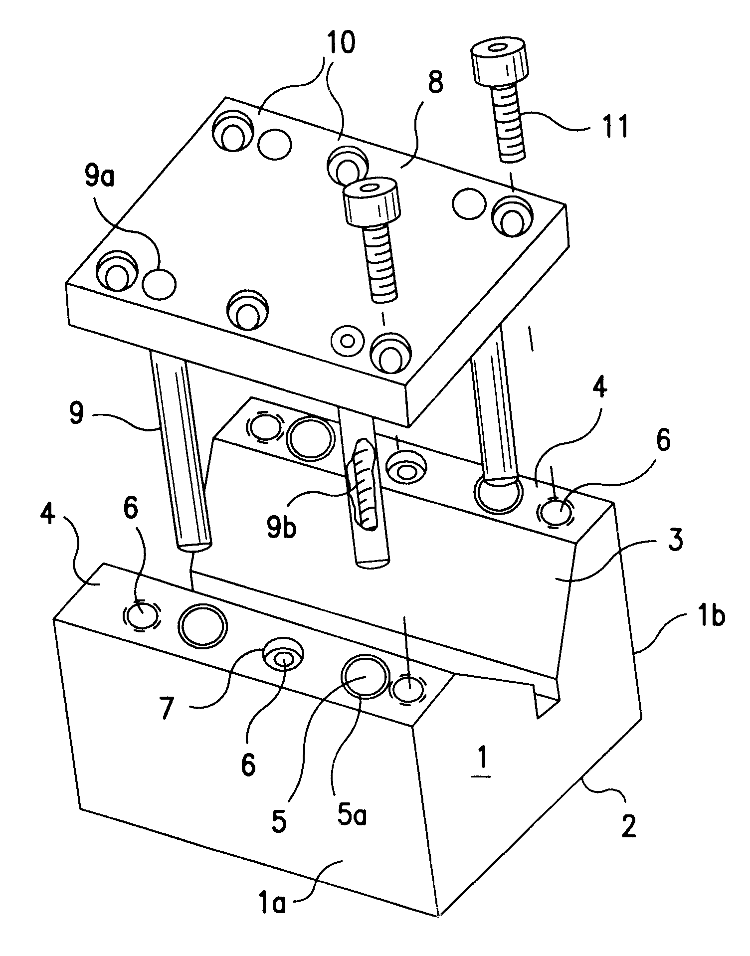
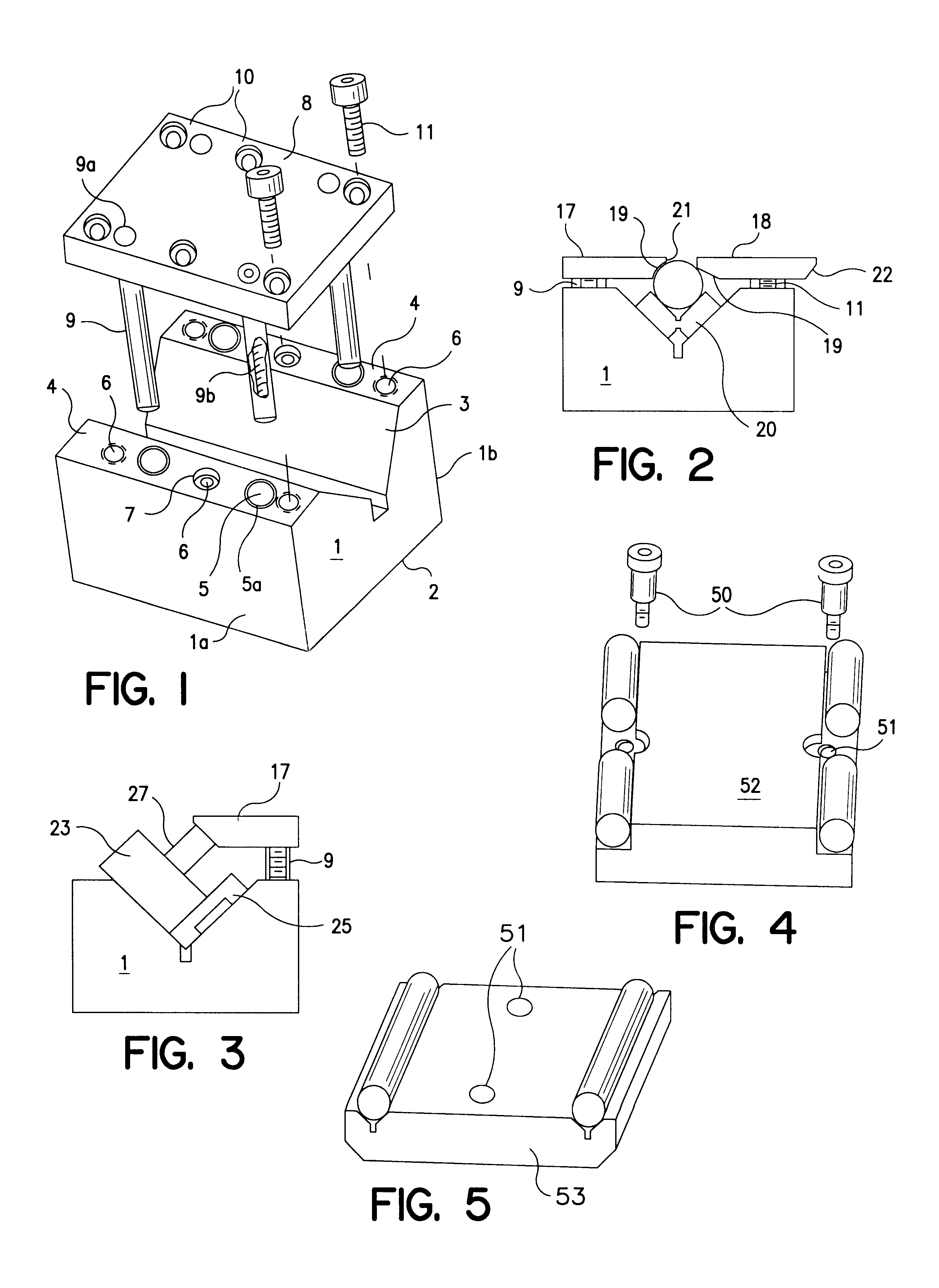
Referring now to FIG. 1, there is shown an exploded view of the preferred embodiment of the invention. The V block portion is generally indicated at 1 and the tangent clamp portion which secures the work is shown at 8. The V block portion is preferably made from cast iron but may be made from other suitable material (cold rolled steel or even hardened tool steel). The clamp portion may be made from mild steel or (oil) hardening steel left in the soft condition. It is preferred to construct the device from nonhardened machinable material. The advantage of this is that the end user may modify either member to facilitate a particular job. The V block fixture 1 has a single V cutout section 3 on one side and a flat base 2 on the opposite side. The V section 3 is parallel to base 2 and the V section is equidistant from sides 1a and 1b and preferably made to a common dimension. For example, the block could be made to exactly a 2.000" dimension. The vertex of the V and the center of the wo...


PUM


Abstract

A workholding device for holding a workpiece securely for machining. One embodiment comprises a V fixture. Embodiments of the present invention are designed to be versatile and to provide the ability to accomplish other tasks beyond workholding, for example, enabling the punching of parts, the dressing of diamond wheels, sharpening drills of a wide range of sizes, and enabling deep hole center drilling.

Description

BACKGROUND OF INVENTIONThe current invention relates to improvements in workholding devices and in V block design in particular. V blocks have been in use in the machine tool industry since at least the 1800's. They are used for holding parts for machining or inspection. Typically a V is machined or ground centrally in a block which has provision for accomodating a horse shoe style clamp to secure the part in the V. More advanced designs enable the block to be held on up to five sides. Nonetheless, the prior art suffers from numerous shortcomings which include low holding power, marred workpieces, bent screws, a high profile--which creates tool interference and a lack of versatility.The screw actuated quill of a lathe's tailstock requires a close tolerance bore in accurate alignment with the headstock. Errors in the vertical alignment are not easily corrected. The clearance between bore and quill and the wear of same is an issue of concern. The stroke depth of the tool is quite limi...

Claims


Application Information

Patent Timeline
Patent Type & Authority Patents(United States)
IPC IPC(8): B25B1/00B25B1/24B25B5/14B25B5/00
CPCB25B1/2452B25B5/147B25B5/006
Inventor ANDRONICA, RANDALL C.
Owner ANDRONICA RANDALL C
Why Eureka
Try Eureka