Three-position electrical switch having a switching element that is movable in axial translation

a technology of axial translation and switching element, which is applied in the direction of earthing switch, switchgear arrangement, air break switch, etc., can solve the problems of inability to interchange, device size is therefore relatively large, and the device cannot provide great flexibility in us

Inactive Publication Date: 2003-05-06
ALSTOM TECH LTD
View PDF4 Cites 24 Cited by
  • Summary
  • Abstract
  • Description
  • Claims
  • Application Information

AI Technical Summary

Benefits of technology

The object of the invention is to provide a three-position electrical switch of structure that is both simple and compact, and that can be used with different interconnection schemes without changing the external structure of the switch.

Problems solved by technology

The resulting devices are thus relatively bulky.
Furthermore, such devices cannot provide great flexibility in use, since once the switch has been installed, it is no longer possible to interchange that one of the two break contacts which can be grounded with the other break contact.

Method used


Image

  • Three-position electrical switch having a switching element that is movable in axial translation
  • Three-position electrical switch having a switching element that is movable in axial translation

Examples


Embodiment Construction

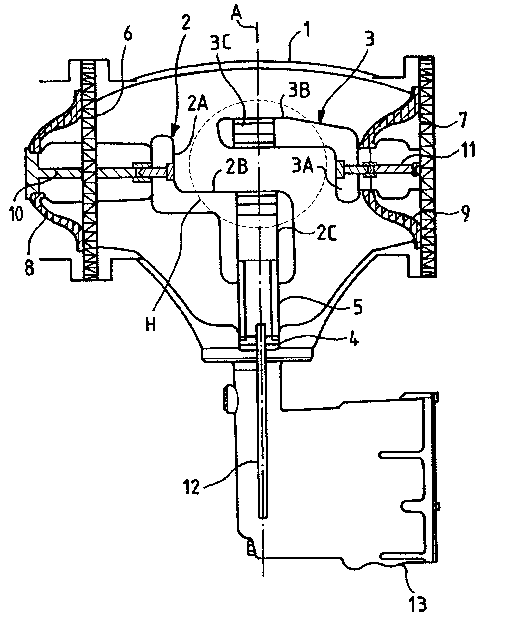
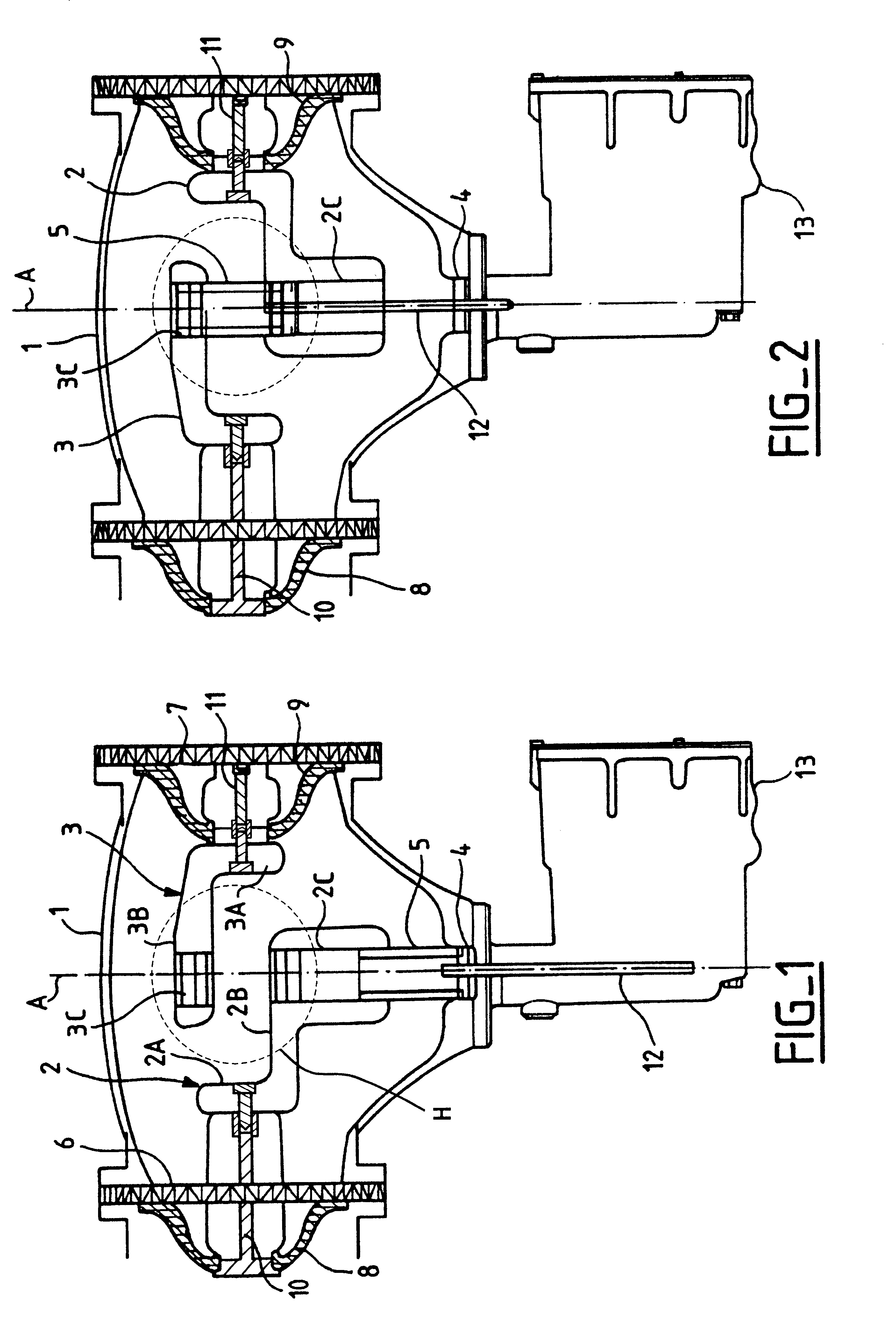
In FIGS. 1 and 2, the three-position electrical switch or disconnector of the invention comprises a metal casing 1 containing a dielectric gas, e.g. SF.sub.6, under a pressure of a few bars, and within which there are fixed first and second break contacts 2 and 3 together with a grounding contact 4. The casing 1 also contains a cylindrical switching element 5 which is movable along an axial direction A.

The casing 1 presents at least first and second openings 6 and 7 placed facing each other on opposite sides of the direction A, each implemented in this example by a perforated disc of insulating material. Each opening 6 or 7 is provided with an electrically insulating support 8 or 9, e.g. implemented in the form of a cone or a disc. Each support 8 or 9 serves to support a current-conducting electrode 10 or 11 on to which a break contact 2 or 3 is removably fixed, e.g. by, means of bolts. As can be seen in figures, each of the electrodes 10 and 11 extends from the center of an opening...


PUM


Abstract

The three-position, gas-insulated, metal-clad electrical switch inside a metal casing includes first and second break contacts, a fixed grounding contact, and a switching element that is movable in an axial direction to interconnect the break contacts. The first and second break contacts and the fixed grounding contact are superposed in the axial direction, and the switching element is moved by a drive rod which passes through the fixed grounding contact, thereby enabling the switching element to occupy each of the three switching positions including a grounding position in which it connects the first break contact to the fixed grounding contact.

Description

The invention relates to a three-position, gas-insulated metal-clad electrical switch, the switch comprising two fixed break contacts each connected to a phase conductor, and a fixed ground contact together with a switching element that is movable in an axial direction to interconnect the fixed contacts.Such an electrical switch is more particularly used for disconnection purposes when interconnecting phase conductors in a high-voltage installation. The switch is then generally referred to as a disconnector, and the three switching positions that can be achieved are conventionally:opening the disconnector without grounding a phase conductor;opening at the disconnector while grounding one of the two break contacts; andclosing the disconnector with the break contacts interconnected.In the state of the art, one of the break contacts is generally grounded by a switching element that is different from the switching element that is used for interconnecting the break contacts. The resultin...

Claims


Application Information

Patent Timeline
Patent Type & Authority Patents(United States)
IPC IPC(8): H02B13/035H02B13/02H01H33/42H01H33/64H02B13/075
CPCH01H31/003H02B13/035H01H31/24
Inventor GUTALJ, VLADIMIR
Owner ALSTOM TECH LTD
Why Eureka
Try Eureka