
CDMA frequency planning for fixed wireless application

a technology of fixed wireless and frequency planning, which is applied in the field of radio telephone systems, can solve the problems of limited tele-traffic bearing capacity in a cdma system, inability to completely eliminate the sho procedures in a fbrt system, and limited tele-traffic bearing capacity

Inactive Publication Date: 2003-05-06
RPX CLEARINGHOUSE
View PDF14 Cites 46 Cited by
  • Summary
  • Abstract
  • Description
  • Claims
  • Application Information

AI Technical Summary

Problems solved by technology

However, due to fading and other phenomena SHO procedures cannot be entirely eliminated in a FBRT system.
In conventional systems tele-traffic bearing capacity is limited by frequency (channel) allocation.
Whereas tele-traffic bearing capacity in a CDMA system is limited by interference.
Categorically, interference within a CDMA system can arise from many sources.
In a CDMA cellular system, each base station not only receives interference from radio telephones in the home cell (intra-cell interference), but also from radio telephones in neighbor cells (inter-cell interference).
Hence, interference arises in both the down-link (base stations to radio telephones) and up-link(radio telephones to base stations) directions.
Another interference source is adjacent channel interference.
However, Adjacent Channel Interference (ACI) from microwave incumbents can cause significant interference.
The microwave incumbent interference can create a problem for CDMA systems in the 1900 MHz PCS frequency spectrum.
However, the microwave incumbent is typically very localized and its impact is restricted to a very few selected number of cells / sectors.
Intermodulation interference both from same block (same operator) and different blocks (different operators) and thermal noise floor are also sources of undesirable interference.

Method used


Image

  • CDMA frequency planning for fixed wireless application
  • CDMA frequency planning for fixed wireless application
  • CDMA frequency planning for fixed wireless application

Examples


Embodiment Construction

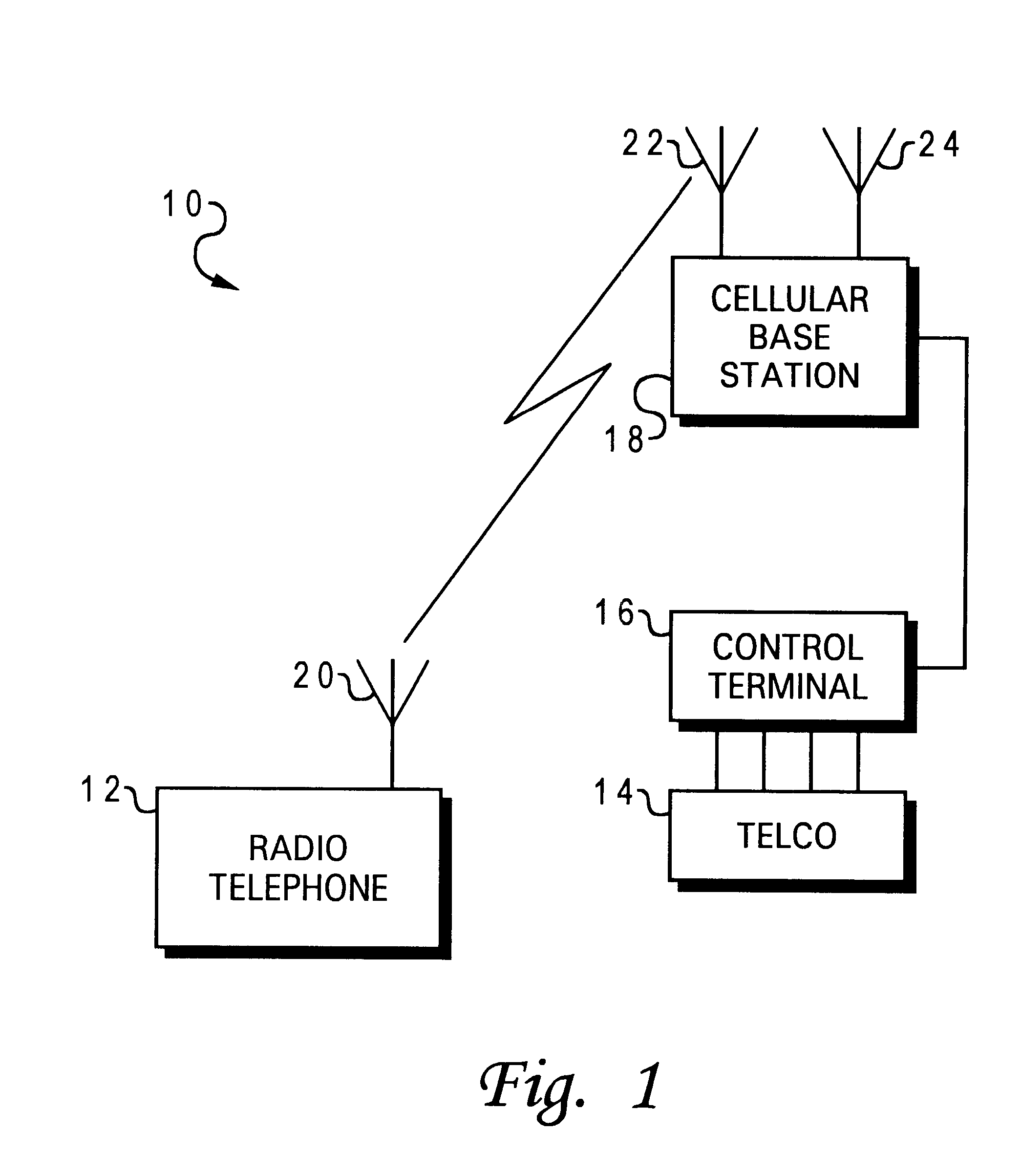
With reference now to the figures and in particular with reference to FIG. 1, there is depicted a block diagram of a radio telephone system 10 in which a preferred embodiment of the present invention may be implemented.

Radio telephone system 10 depicted in FIG. 1 includes a telephone company phone system (TELCO) 14 or mobile switch center (MSC), connected by telephone landlines to a control terminal 16 which in turn is coupled, also by telephone landlines, to a cellular base station 18 that is located in a cell of a radio telephone system.

Those skilled in the art will appreciate that radio telephone system 10 is one type of a communication system which may be utilized in accordance with a preferred embodiment of the present invention. Radio telephone system 10 as described herein is one such embodiment and is presented for illustrative purposes only.

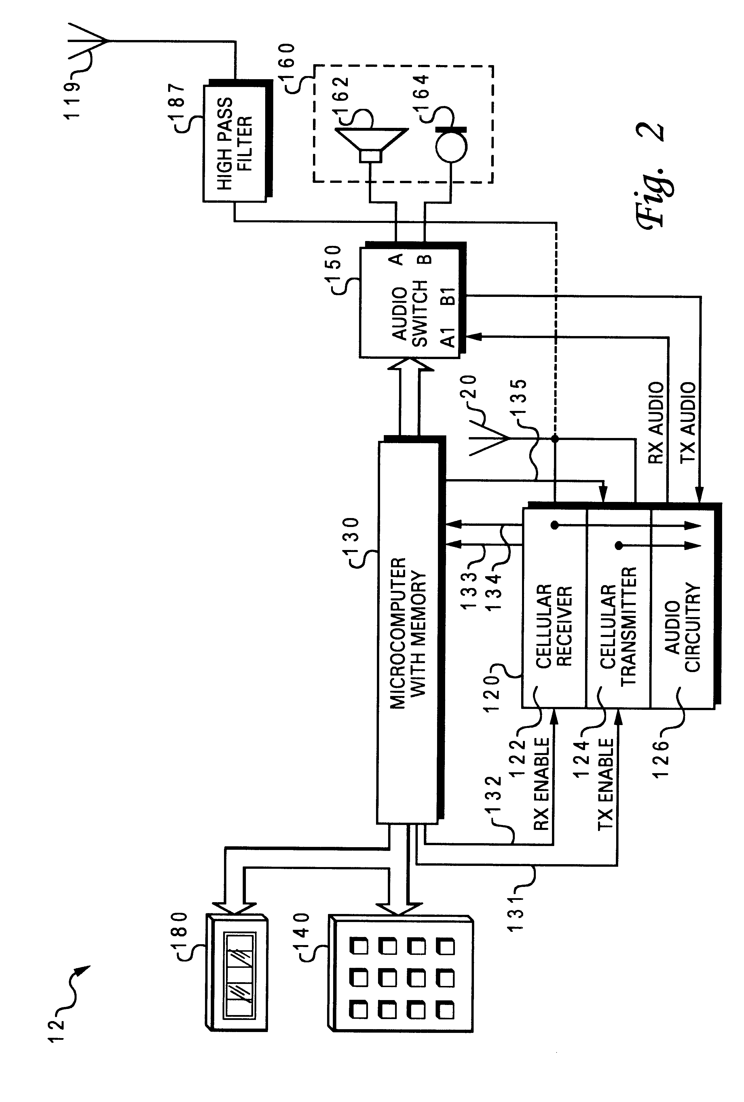
Radio telephone 12 communicates with cellular base station 18 via antennas 22 and 20. Antennas 22 and 20 can be implemented as telescop...


PUM


Abstract

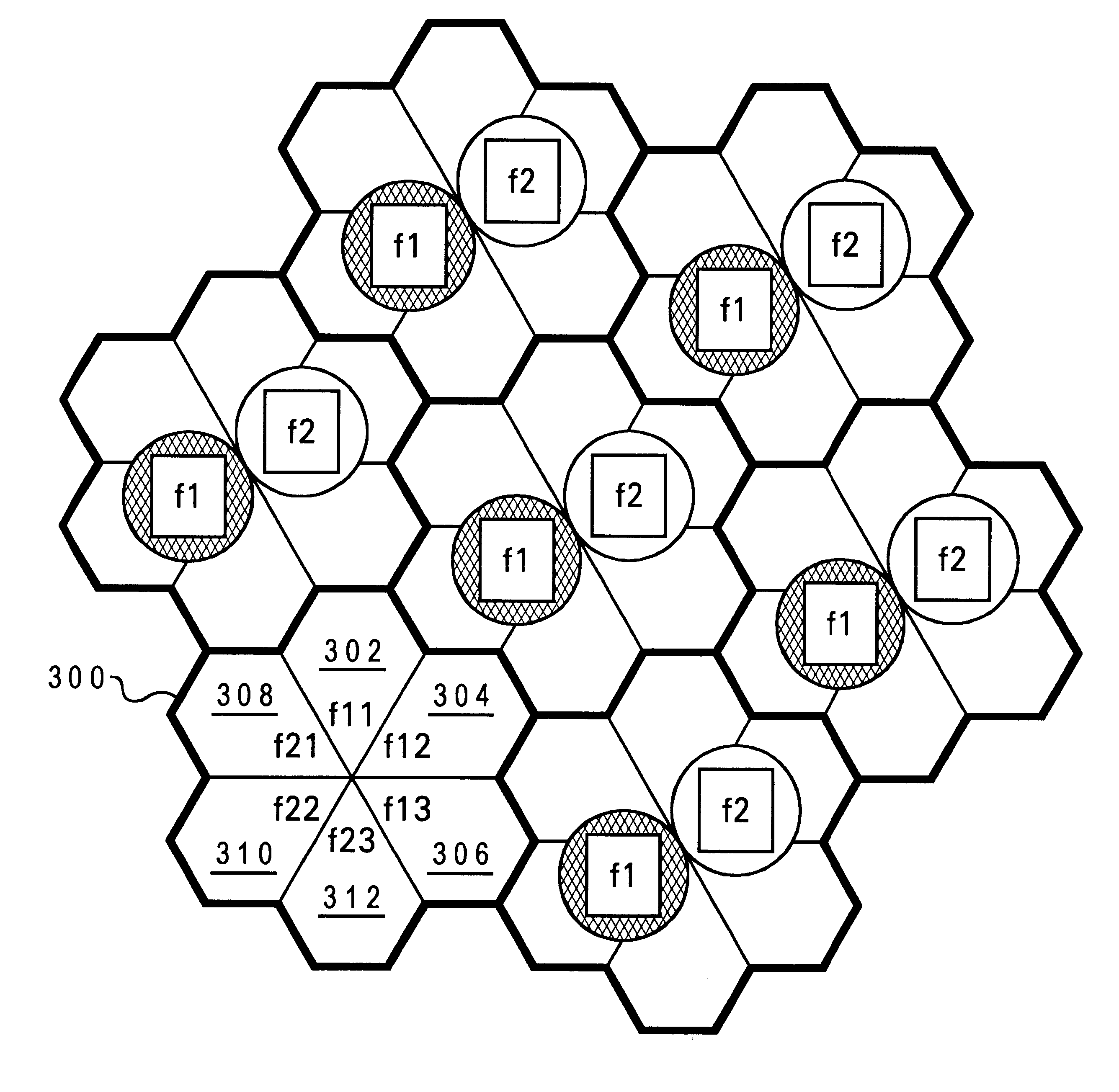
The foregoing objects are achieved as is now described. A method for evaluating frequency plans for a CDMA based communication system having fixed base radio telephones is provided. The method begins by determining locations of a plurality of antennas. The plurality of antennas provide a coverage area for radio telephones. Then the method generates locations of radio telephones within the coverage area. Next, a distance from each radio telephone to the antennas is calculated. Then frequencies are allocated to the antennas. The resulting communication parameters between the radio telephones and the antennas are evaluated. Next, the coverage area which provides optimum power control to each radio telephone is determined. A frequency reuse factor is calculated to determine the efficiency of the allocated frequencies such that frequency allocation plans can be analyzed to determine efficient frequency planning.

Description

1. Technical FieldThe present invention relates in general to a radio telephone system and in particular to a method and system for allocating frequencies for fixed location radio telephones. Still more particularly, the present invention relates to a method and system for frequency planning for a communication system comprised of fixed wireless application.2. Description of the Related ArtEvolving nations are implementing telephone based communication systems. It has been determined that the most economical method for installing a telephone system where no previous system exists is to designate a fixed base wireless telephone for each subscriber.A Fixed Base Radio Telecommunication (FBRT) topology is commonly referred to as Fixed Wireless Application (FWA) or Wireless Local Loop (WLL). FWA and WLL allow a telephone company to take advantage of the wireless technology as a substitute for the last several miles of transmission line to bring telephony into a household and to users. Th...

Claims


Application Information

Patent Timeline
IPC IPC(8): H04Q7/36H04W16/02H04W16/12H04W16/24
CPCH04W16/02H04W16/12H04W52/283H04W4/08H04W16/24H04W72/0453H04W28/18H04W64/00H04W28/04Y02D30/70
Inventor WONG, TONY W.
Owner RPX CLEARINGHOUSE
Learn More