Fuel injection device having heater

a fuel injection device and heater technology, which is applied in the direction of combustion-air/fuel-air treatment, combustion types, lighting and heating apparatus, etc., can solve the problems of difficult to closely fit the heater cylinder, the heat of the heater 103 is not easily conducted to the fuel, and the fuel cannot be easily injected during cold start-up of the engin

Inactive Publication Date: 2003-05-13
DENSO CORP
View PDF9 Cites 66 Cited by
  • Summary
  • Abstract
  • Description
  • Claims
  • Application Information

AI Technical Summary

Problems solved by technology

Particularly, the fuel injected during cold start-up of the engine cannot be easily atomized and tends to adhere, for example, to an inner wall of an intake pipe.
Thus, heat of a heater 103 is not easily conducted to the fuel located inside the nozzle needle 101.
However, if the ceramic heater or the like, which has a relatively low mechanical strength with respect to a tensile force, is used as the cylindrical heater 103, it is difficult to closely fit the cylindrical heater 103 to the valve body 104 by press fitting the cylindrical heater 103 to an outer wall of the valve body 104 because of the relatively low mechanical strength of the ceramic heater with respect to the tensile force.

Method used


Image

  • Fuel injection device having heater
  • Fuel injection device having heater
  • Fuel injection device having heater

Examples


first embodiment

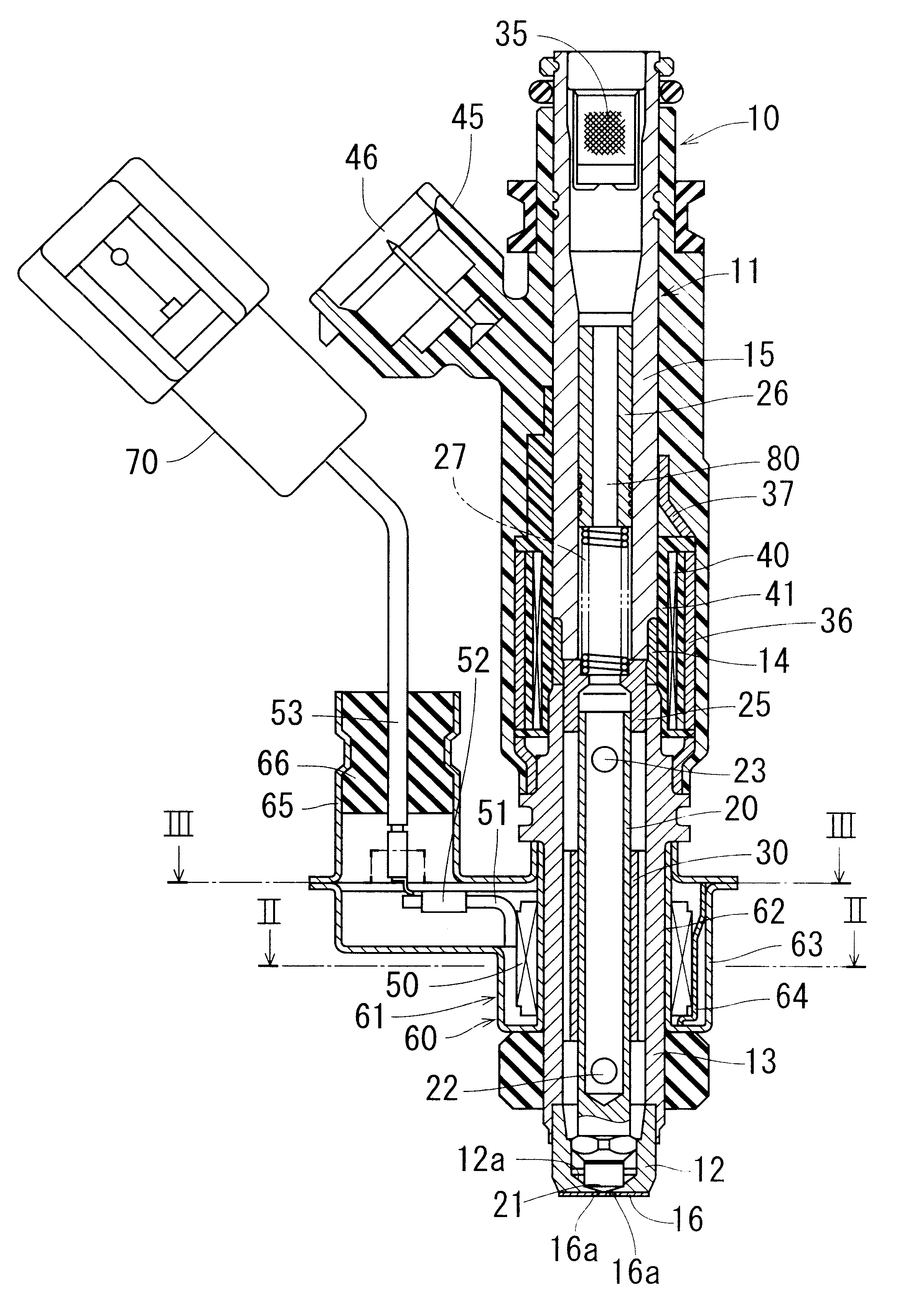
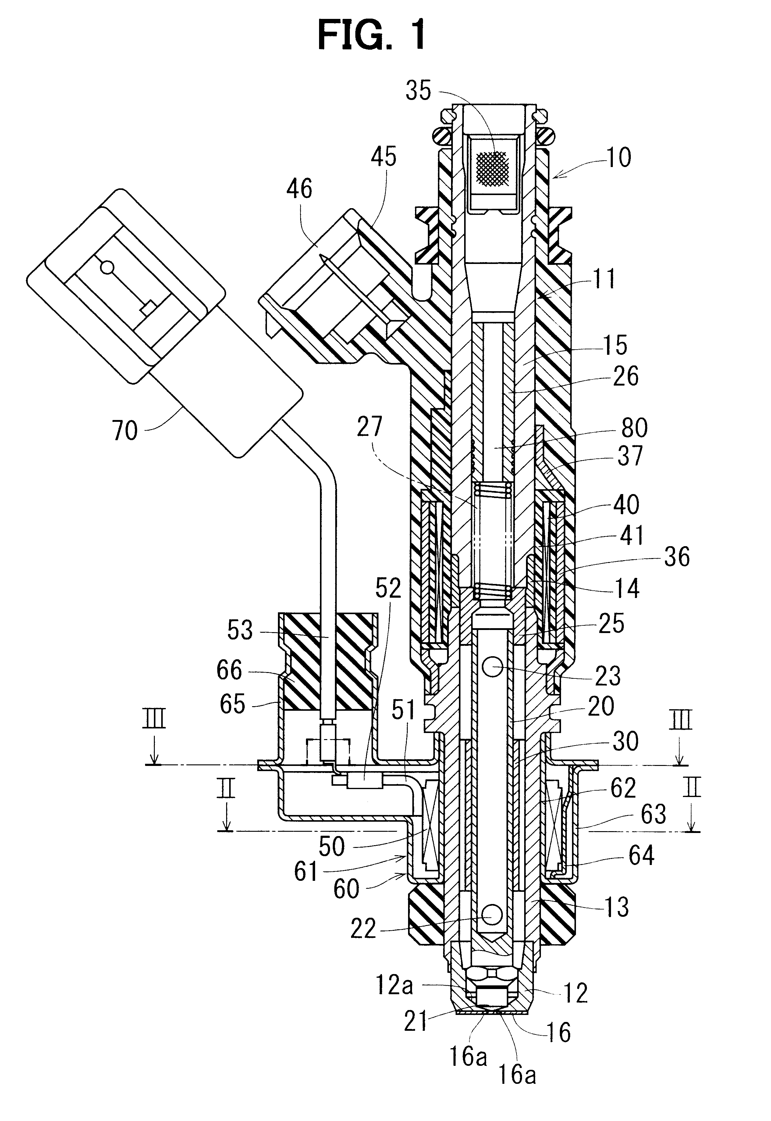
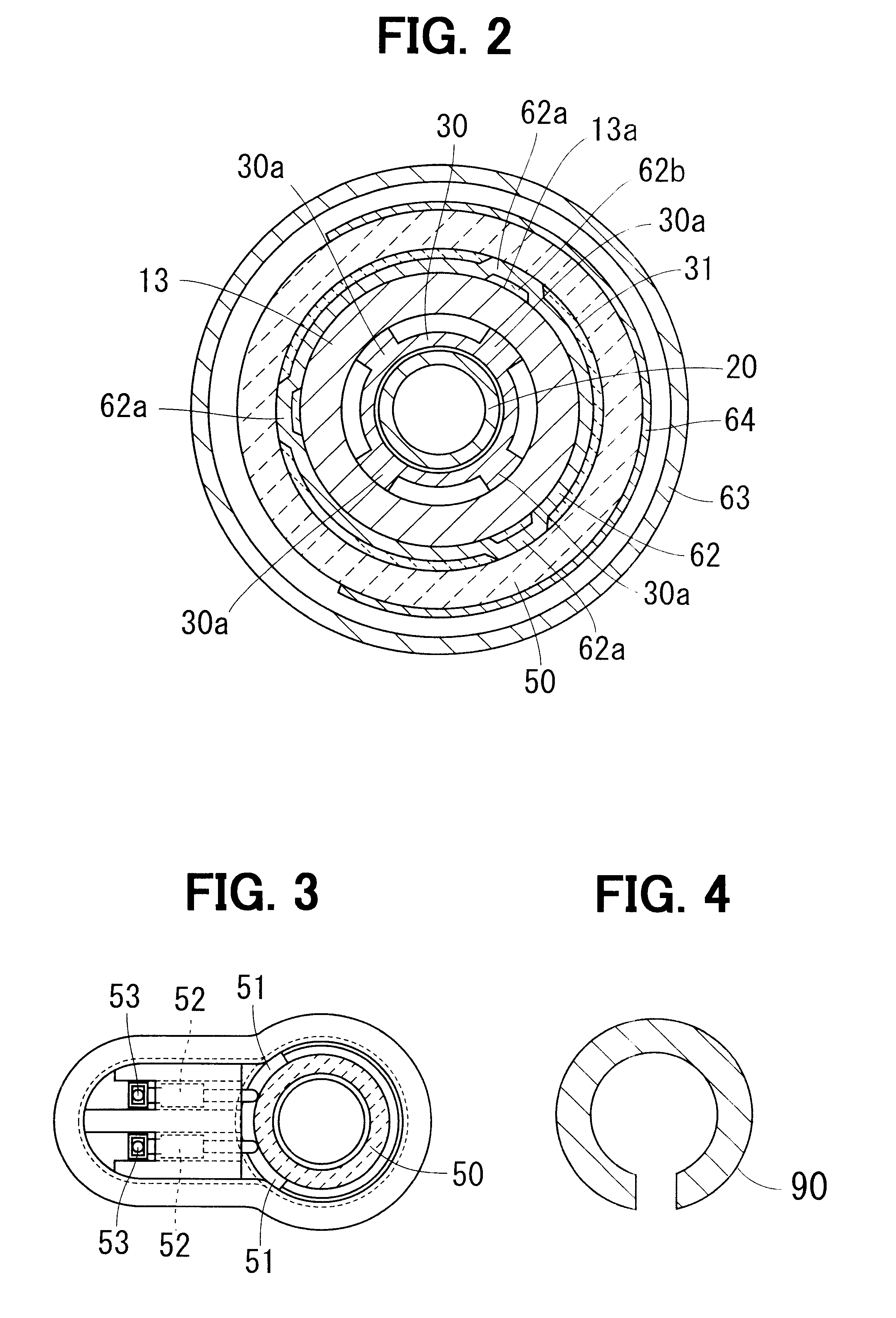
FIG. 1 shows a fuel injector (acting as a fuel injection device of the present invention) 10 according to the present invention. A valve housing 11 of the injector 10 includes a valve body main body 12, a first tubular magnetic portion 13, a non-magnetic tubular portion 14 and a second tubular magnetic portion 15. The valve body main body 12 and the first magnetic portion 13 constitute a valve body. The valve body main body 12 includes a valve seat 12a, against which an engaging portion (base portion) 21 of a nozzle needle (acting as a valve member of the present invention) 20 can be seated. The non-magnetic portion 14 is placed between the first magnetic portion 13 and the second magnetic portion 15 and prevents a short circuit of a magnetic flux therebetween. The valve body main body 12 is welded to an inner wall of the first magnetic portion 13 on a fuel injecting side thereof. An injection hole plate 16 is welded to a bottom end outer wall of the valve body main body 12, which i...

second embodiment

FIG. 5 shows a fuel injector 310 according to a second embodiment of the present invention. A valve housing 311 is shaped into a tubular form and has magnetic and non-magnetic portions. The valve housing 311 is made, for example, of a compounded magnetic material. The valve housing 311 has a fuel passage 370. A valve body main body 315, a nozzle needle (acting as a valve member of the present invention) 320, a spring (acting as an urging means of the present invention) 326, a stationary core 330, an adjusting tube 331, and a filter 339 are arranged in the fuel passage 370.

The valve housing 311 is an integral body and has a first magnetic portion 312, a non-magnetic portion 313 and a second magnetic portion 314, which are arranged in this order in a downstream-to-upstream direction of fuel flow (i.e., in a bottom-to-top direction in FIG. 1). The first magnetic portion 312 and the second magnetic portion 314 of the valve housing 311 are magnetized. The non-magnetic portion 313 of the ...

third embodiment

FIGS. 12 and 13 show a fuel injector 310 according to a third embodiment of the present invention. In the third embodiment, a first magnetic portion 121 is provided in place of the first magnetic portion 312 of the second embodiment. The first magnetic portion 121 forms a relatively thick portion on a cylindrical inner wall of the first magnetic portion 121. In other words, the first magnetic portion and the heat transfer tube of the previous embodiments are integrated into the first magnetic portion 121, and the thick portion is formed in the inner wall of the first magnetic portion 121. In a cross-section of the thick portion, the thick portion has a corrugated inner wall surface, as shown in FIG. 13. Axial ends 1211, 1212 of the thick portion of the first magnetic portion 121 are tapered or slanted and are connected to relatively thin portions of the first magnetic portion 121, respectively. With this arrangement, the flow passage is narrowed, and thus a contact efficiency betwee...


PUM


Abstract

A nozzle needle has a hollow tubular form having a closed base end. A heat transfer tube is press fitted into a first magnetic portion. The heat transfer tube surrounds an outer peripheral surface of the nozzle needle. A ceramic heater is formed as an integral cylindrical body by sintering a ceramic material together with a heat generating resistive element. A case covers the heater and protects the heater from externally applied water. An inner tube of the case is resiliently engaged with both the heater and the first magnetic portion. Heat of the heater is conducted to the nozzle needle through the inner tube, the first magnetic portion and the heat transfer tube to heat fuel inside the nozzle needle.

Description

This application is based on and incorporates herein by reference Japanese Patent Application No. 2001-95382 filed on Mar. 29, 2001 and Japanese Patent Application No. 2001-239086 filed on Aug. 7, 2001.1. Field of the Invention:The present invention relates to a fuel injection device for injecting fuel into a corresponding cylinder of an internal combustion engine.2. Description of Related Art:Recently, vehicle emission regulations have become increasingly stringent. In order to reduce noxious components in exhaust gases of an internal combustion engine (hereinafter, the internal combustion engine will be referred to as an engine), it is important to atomize fuel, which is injected through fuel injection holes of a fuel injection device (hereinafter, the fuel injection device will be referred to as a fuel injector) into a corresponding cylinder of the engine. One effective measure for atomizing the fuel is as follows. That is, fuel is first heated and is then injected through the in...

Claims


Application Information

Patent Timeline
Patent Type & Authority Patents(United States)
IPC IPC(8): F02M53/06F02M53/00F02M51/06F23K5/20F16K49/00F23K5/02F23K5/14F02M31/125F02M31/02
CPCF02M51/0682F23K5/20F16K49/002F23K5/147F02M53/06F02M31/125
Inventor HOKAO, TAKAYUKITARUSAWA, MIYUKITAKEDA, HIDETOHASEGAWA, HIROSHI
Owner DENSO CORP
Why Eureka
Try Eureka