Standby power system

a power system and standby technology, applied in the direction of engine starters, machines/engines, emergency power supply arrangements, etc., can solve the problems of delay in switching over to such engine-driven auxiliary power supplies, inability to assume full load, damage to delicate electronic instruments, etc., to achieve smooth and efficient power transfer, safe and convenient use of large flywheels

Inactive Publication Date: 2003-05-13
FARKAS OTTO
View PDF19 Cites 44 Cited by
  • Summary
  • Abstract
  • Description
  • Claims
  • Application Information

AI Technical Summary

Benefits of technology

It is a main object of the present invention to provide an auxiliary power source that can take over supplying power to a load when a main source of power goes away or falls below a specified limit and does so in a manner that does not adversely affect the load.
The coupling unit also permits matching the output of the engine to the desired input of the motor / generator while allowing the engine to operate at its most efficient level. The system of the present invention also permits a flywheel to operate at any selected rotational speed, even if that speed differs from the output rotational speed of either the engine or the motor / generator. Still further, the auxiliary power unit of the present invention is amenable to being ganged together with other auxiliary power units to provide large amounts of power when necessary.

Problems solved by technology

This situation may be caused by a power loss at the utility, a break in a supply line or the like.
Interruptions in power can damage delicate electronic instruments as well as wipe out computer memories.
However, it is not sufficient to merely supply power to a load during main power supply downtime, such power should be supplied in a manner that is most efficient and does not damage equipment during a changeover from the main power source to the auxiliary power source.
This is especially true if the equipment is subject to a number of such spikes which might occur if the main power source is subject to variations in output.
However, even a well-primed and pre-heated thermal engine can require as much as two to three seconds to come up to operating speed and cannot assume full load until such time as it is operating at its operating speed.
Thus, there is a delay in switching over to such engine-driven auxiliary power supplies that is associated with an inherent condition of the engine that cannot be changed in any significant manner.
However, two to three seconds is an eternity when electronic equipment is concerned.
During that delay time, electronic memories can be totally lost, equipment shut off in a manner that damages that equipment or equipment associated therewith, and significant spikes developed, among many other undesirable results.
Most flywheel systems are not sufficient to supply power to large loads such as might be found in large businesses or the like, even for the short time associated with a change over to an auxiliary power system.
Increasing the size of a flywheel is not as efficient as increasing the speed of rotation due to the relationship between mass and energy and between velocity and energy.
However, even beyond that, increasing the size of a flywheel may not be efficient from the standpoint of the structures associated with the flywheel.
These structures must be large enough to accommodate the flywheel and if large amounts of energy are required from the flywheel, the structures associated with the flywheel may become unwieldy.
However, some flywheel speeds in flywheels associated with prior art systems are limited by the speed of rotation of the equipment associated with the flywheel.
Accordingly, it may be difficult and complicated to adapt a flywheel rotating in a horizontal plane to couple to a shaft that is rotating in a vertical plane.
While the art does contain some examples of auxiliary power systems having large flywheels, such systems have many parts, are complex, expensive, not fully reliable and often take up a large amount of space, while not being as efficient as possible.
Accordingly, the engines used in existing auxiliary power systems must be de-rated in horsepower and thus lose efficiency.

Method used


Image

  • Standby power system
  • Standby power system
  • Standby power system

Examples


Embodiment Construction

Other objects, features and advantages of the invention will become apparent from a consideration of the following detailed description and the accompanying drawings.

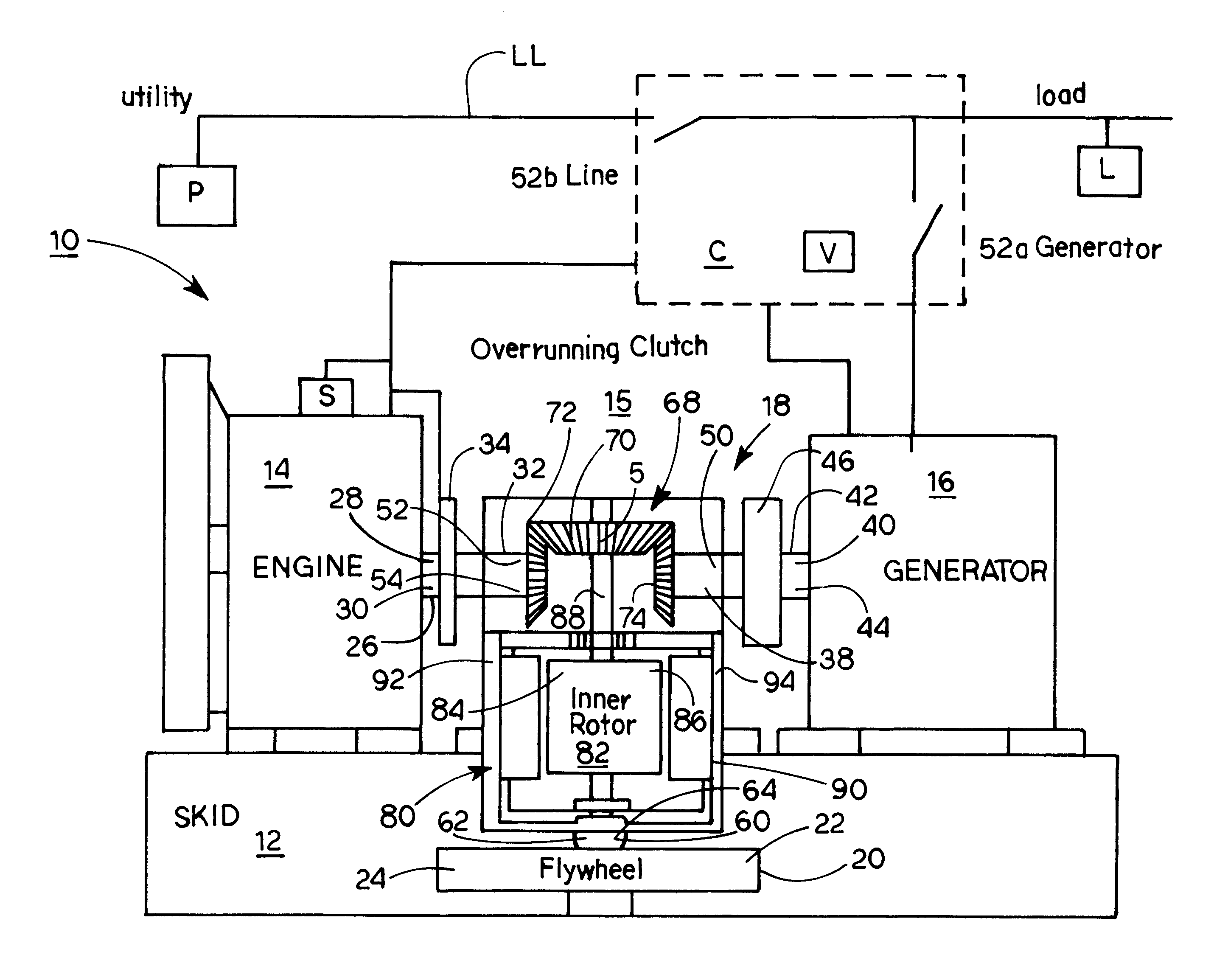
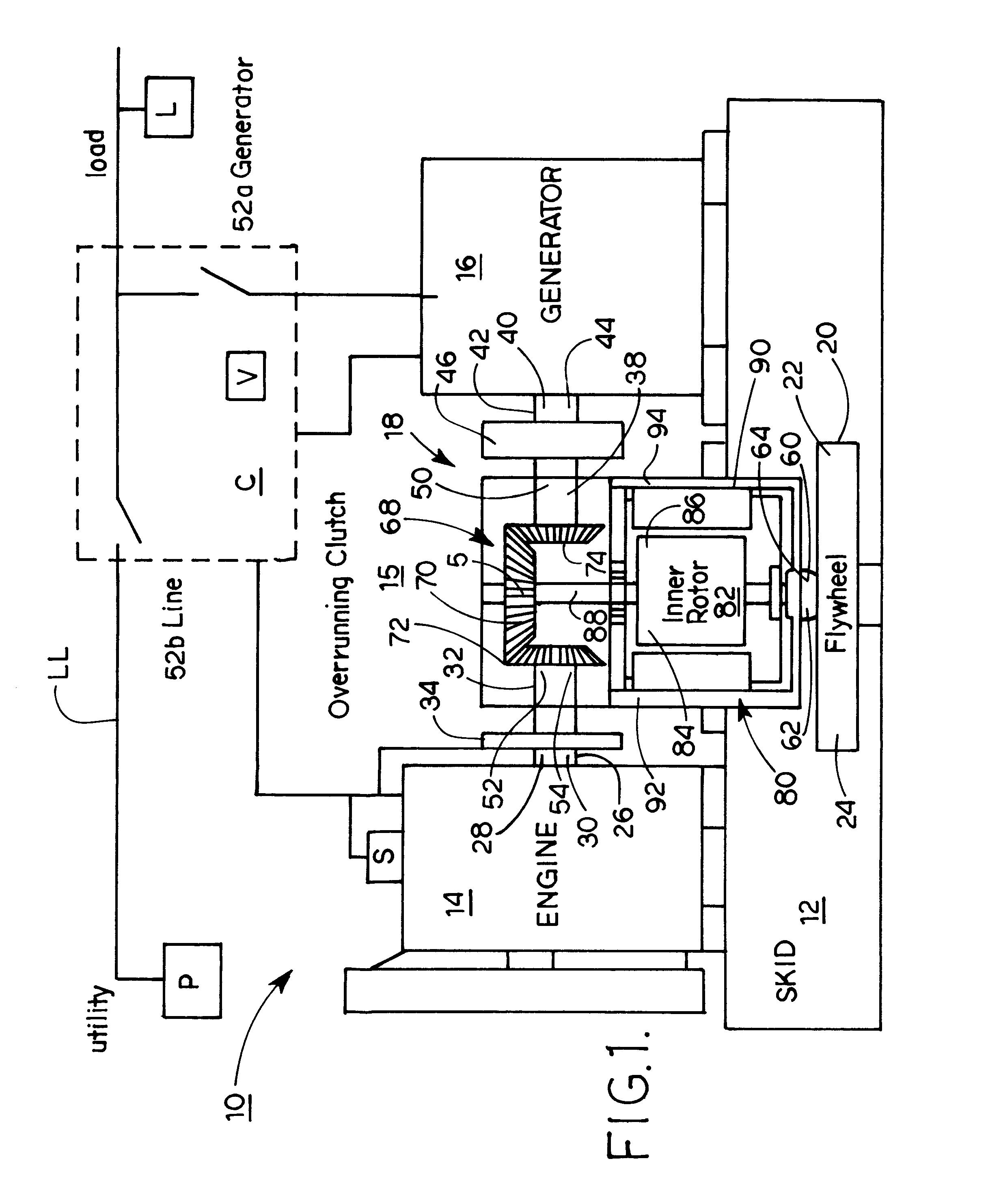
Shown in FIG. 1 is a first form of a standby power generating system 10 embodying the present invention. A load L such as a hospital, business or the like is powered from a main power source P, such as a utility or the like via a load line LL. During normal operation of power source P, load L receives all of its power via load line LL from source P. However, in various situations, such as storms, equipment failure or the like, there are times when the power level from source P drops below a value that can safely power the equipment represented by load L. This value can be pre-set according to the equipment represented by load L. When the power level from source P drops below this pre-set level, system 10 will take over and supply the necessary power to load L via line LL. Until that time, system 10 is in a stand-by mode...


PUM


Abstract

A standby power system includes a flywheel that rotates in a horizontal plane and is coupled to an engine and a motor / generator that have horizontally oriented shafts which rotate in vertical planes. A coupling changes the direction of rotation to couple the flywheel to the engine and / or to the motor / generator. The flywheel can rotate at speeds different from the speeds of rotation of the shafts and several systems can be ganged together to supply power. The coupling can include mechanical, electromechanical and hydraulic elements.

Description

The present invention relates to the general art of electrical transmission or interconnection systems, and to the particular field of substitute or emergency power supplies.In many instances, it is desirable to provide an emergency power system which will automatically supply continuous auxiliary electric power when a main source of power, such as a utility, falls below a certain level. This situation may be caused by a power loss at the utility, a break in a supply line or the like. There are many examples of situations that require a continuous supply of power, even when a main source of power is down. Hospitals, telecommunications centers, industrial plants, as well as any computer user all require a continuous source of power. Interruptions in power can damage delicate electronic instruments as well as wipe out computer memories. The loss of all or a portion of a main power supply occurs in the United States, and can be common in developing countries.Therefore, the art has seve...

Claims


Application Information

Patent Timeline
Patent Type & Authority Patents(United States)
IPC IPC(8): F02B75/06F02B75/00F02B63/04F02B63/00H02K7/02H02K7/00H02K7/18
CPCF02B63/04F02B75/06H02K7/025Y02E60/16H02K7/1815F02B2063/045
Inventor FARKAS, OTTO
Owner FARKAS OTTO
Why Eureka
Try Eureka