Operating and locking mechanisms for handcuffs

a technology of operating mechanism and locking mechanism, which is applied in the direction of handcuffs, constructions, building locks, etc., can solve the problems of mechanism not being secure and utterly defeating the purpose of handcuffs

Inactive Publication Date: 2003-05-27
FTD LLC
View PDF21 Cites 23 Cited by
  • Summary
  • Abstract
  • Description
  • Claims
  • Application Information

AI Technical Summary

Benefits of technology

It is believed that the specific locations of the operating and locking mechanisms of this invention within separate machinery spaces as well as structural features of the swing arm and the machinery spaces, serve to prevent the insertion of any object, such as a shim, between the swing arm teeth and the gear teeth and / or between the locking mechanism and the gear teeth. Even if any object is inserted between any of the various teeth and mechanisms, then, It is further believed, that the shim will become wedged in the teeth and or gears which will operate to prevent any rotation of the gears and thus prevent any rotation of the swing arm.
It is clear that the operating mechanism of the present invention replaces the pawl of the prior art with a gear or gears, which are constantly, and fully engaged with the teeth of the swing arm. The operating gears can not be jimmied open by the insertion of a metal or plastic shim. Additionally, the locking mechanism utilizes a yoke that is positioned and formed to make it difficult to pick by anyone.

Problems solved by technology

It is apparent, then, that a handcuff, or handcuffs, which can be opened and removed by the person being restrained, or by any other unauthorized person, either by force or by device, utterly defeats the purpose of the handcuffs.
These mechanisms are not secure because they can be opened by force, for example by jimmying and jarring.

Method used


Image

  • Operating and locking mechanisms for handcuffs
  • Operating and locking mechanisms for handcuffs
  • Operating and locking mechanisms for handcuffs

Examples


Embodiment Construction

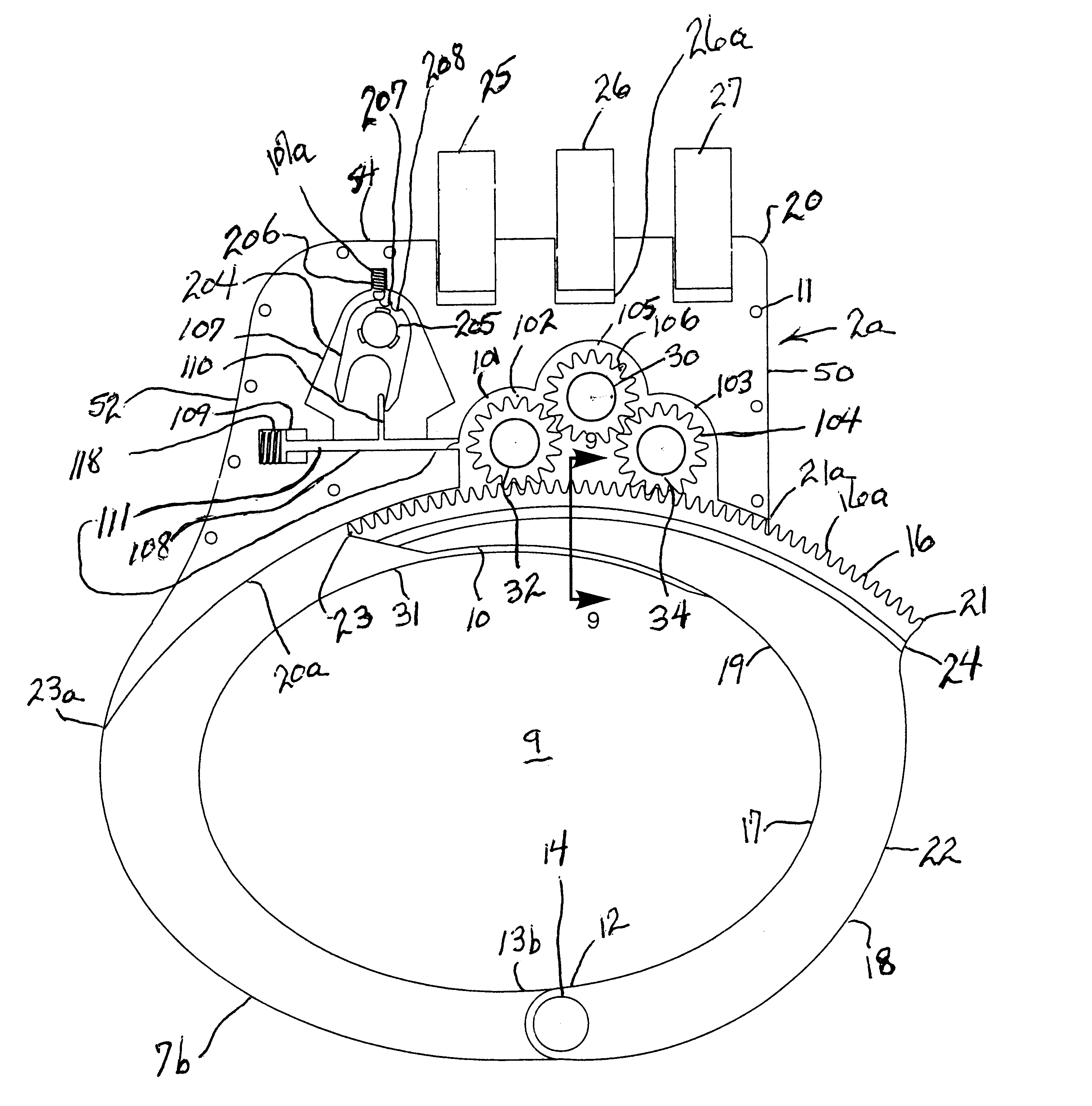
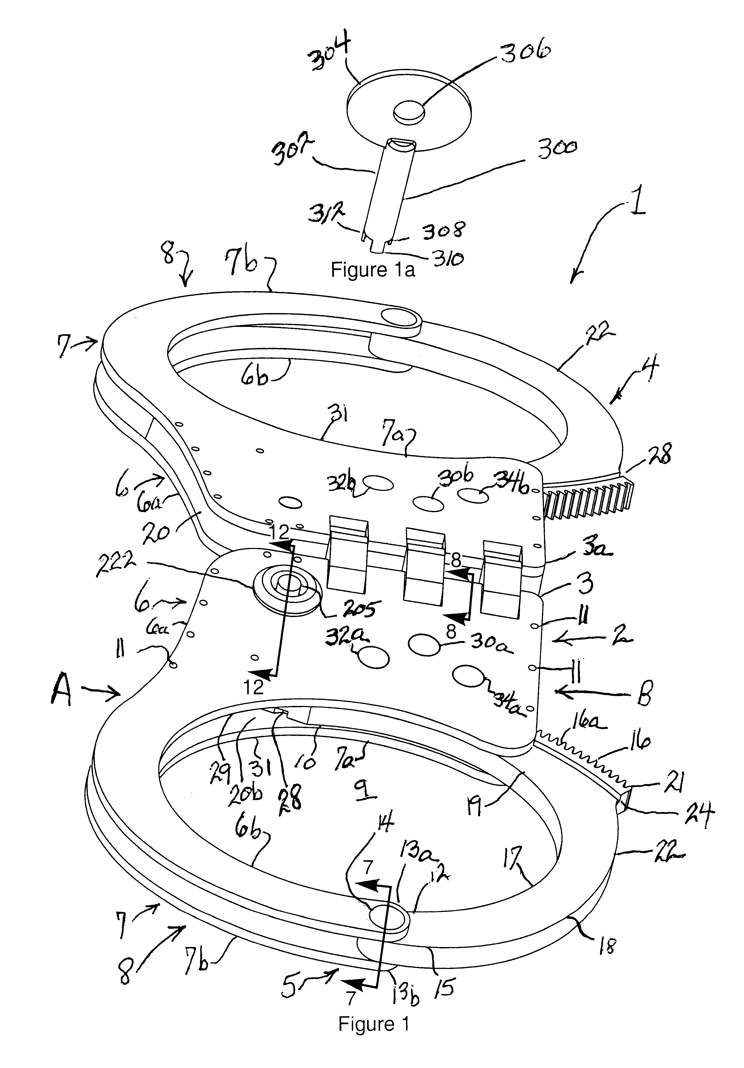
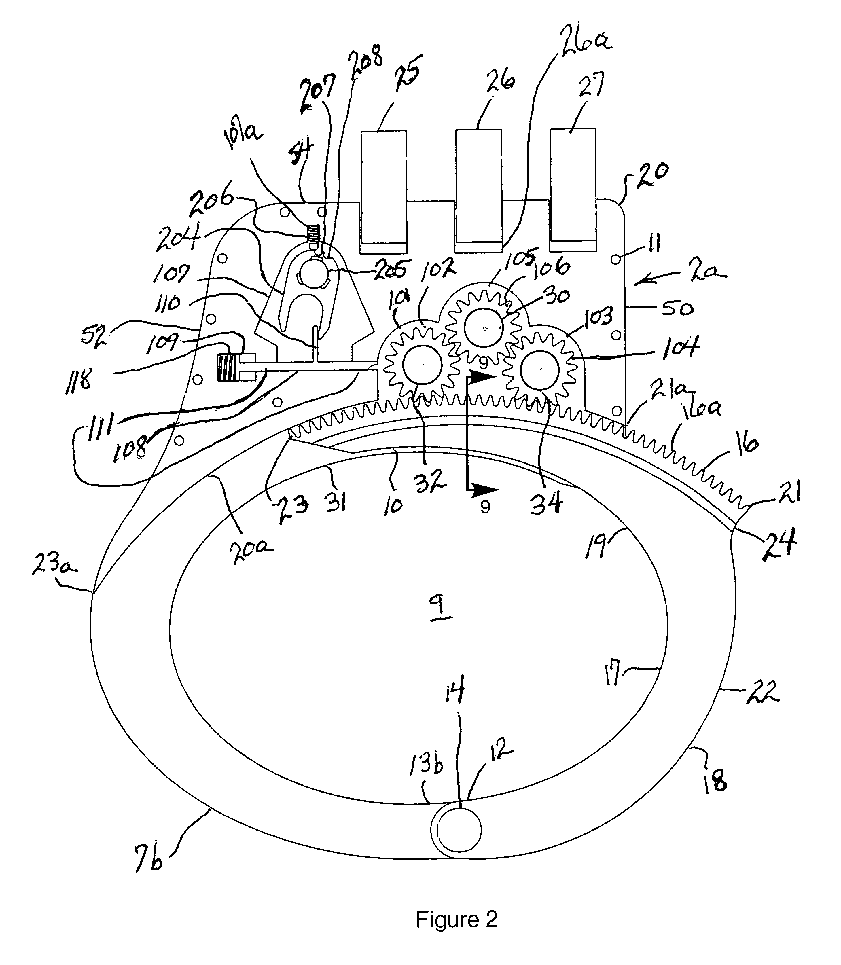
Referring now to the Figures, and particularly to FIGS. 1-4, there is shown a set of handcuffs 1 broadly comprised of first handcuff 2 and second handcuff 4 positioned end-to-end and flexibly connected together. In this regard, proximal end 3 of handcuff 2 is spaced apart from and flexibly connected to proximal end 3a of handcuff 4 by coupling links 25, 26 and 27. Handcuff 2 and handcuff 4 can be identical in construction and operation and are shown as such in FIG. 1, accordingly, the following description of handcuff 2 is fully applicable to handcuff 4. Therefor, only handcuff 2 is described in detail. Reference is made to handcuff 4, or any of its elements, only if clarification is believed to be served by such reference.

Handcuff 2 is an apparatus comprised of the combination of planar top plate 6, which is aligned with and parallel to, planar bottom plate and 7, housing block 20, containing the operating and locking mechanisms of this invention, and curvilinear swing arm 22. Plat...


PUM


Abstract

A set of handcuffs having an improved locking mechanism. The critical element of the locking mechanism is the utilization of a locking gear set that replaces the conventional pawl. The teeth in the locking arm are matched to the locking gear set and are always in constant and full contact with the locking gear set. This invention also uses a cam / cylinder locking device that controls the movement of the locking gear set. In the normal cam position the locking gear set will only turn in one direction, thus enabling the locking arm to close. In the second cam position the locking gear set will not turn in either direction. The cam can be rotated, through the use of a cylindrical key, in either directions. Rotation in one direction will select one of two locking positions. Rotation of the cylindrical key in the opposite direction will free locking gear set to rotate in the opposite direction thus disengaging the locking arm.

Description

1. Technical Field of the InventionThis invention broadly relates to locking devices. The invention further relates to locking devices useful to physically restrain the movement by an individual of his or her arms and / or legs. This invention more particularly relates to mechanical restraining devices referred to in the art as "handcuffs." This invention specifically relates to an operating mechanism and to a locking mechanism for a handcuff.2. Description of the Prior Art and Problems SolvedIt is known in the art that a handcuff is an apparatus, usually made of metal, which, when employed, is ordinarily placed around the wrist or ankle of an individual. The apparatus, can be, and usually is, directly connected to another such device by a bridge, such as a chain, a link, or a bar, to thereby form a combination of such devices. The combination is referred to in the art and herein as "handcuffs" or as a "set of handcuffs."It is also known in the art to place handcuffs upon an individua...

Claims


Application Information

Patent Timeline
Patent Type & Authority Patents(United States)
IPC IPC(8): E05B75/00
CPCE05B75/00Y10T70/404
Inventor TAPER, WILLIAM D.FROST, GARY S.
Owner FTD LLC
Why Eureka
Try Eureka