Pointing stick device and the manufacturing method thereof

a technology of pointing stick and manufacturing method, which is applied in the direction of mechanical control device, instrument, force/torque/work measurement apparatus, etc., can solve the problems of substrate deformation, inconvenient use of notebook computer system, and inability to adapt to notebook computer system

Inactive Publication Date: 2003-05-27
BENQ CORP
View PDF10 Cites 25 Cited by
  • Summary
  • Abstract
  • Description
  • Claims
  • Application Information

AI Technical Summary

Benefits of technology

A pointing stick for use to control the c...

Problems solved by technology

The traditional cursor controller, e.g. joystick or mouse, is not suitable for the notebook type computer system due to its size.
However, for the above-mentioned pointing stick, the sensors are attached onto the substrate, and the deformation of the substrate is caused by the external force on the stick.
These requirement place limitation on the types of material that can be us...

Method used


Image

  • Pointing stick device and the manufacturing method thereof
  • Pointing stick device and the manufacturing method thereof
  • Pointing stick device and the manufacturing method thereof

Examples


Embodiment Construction

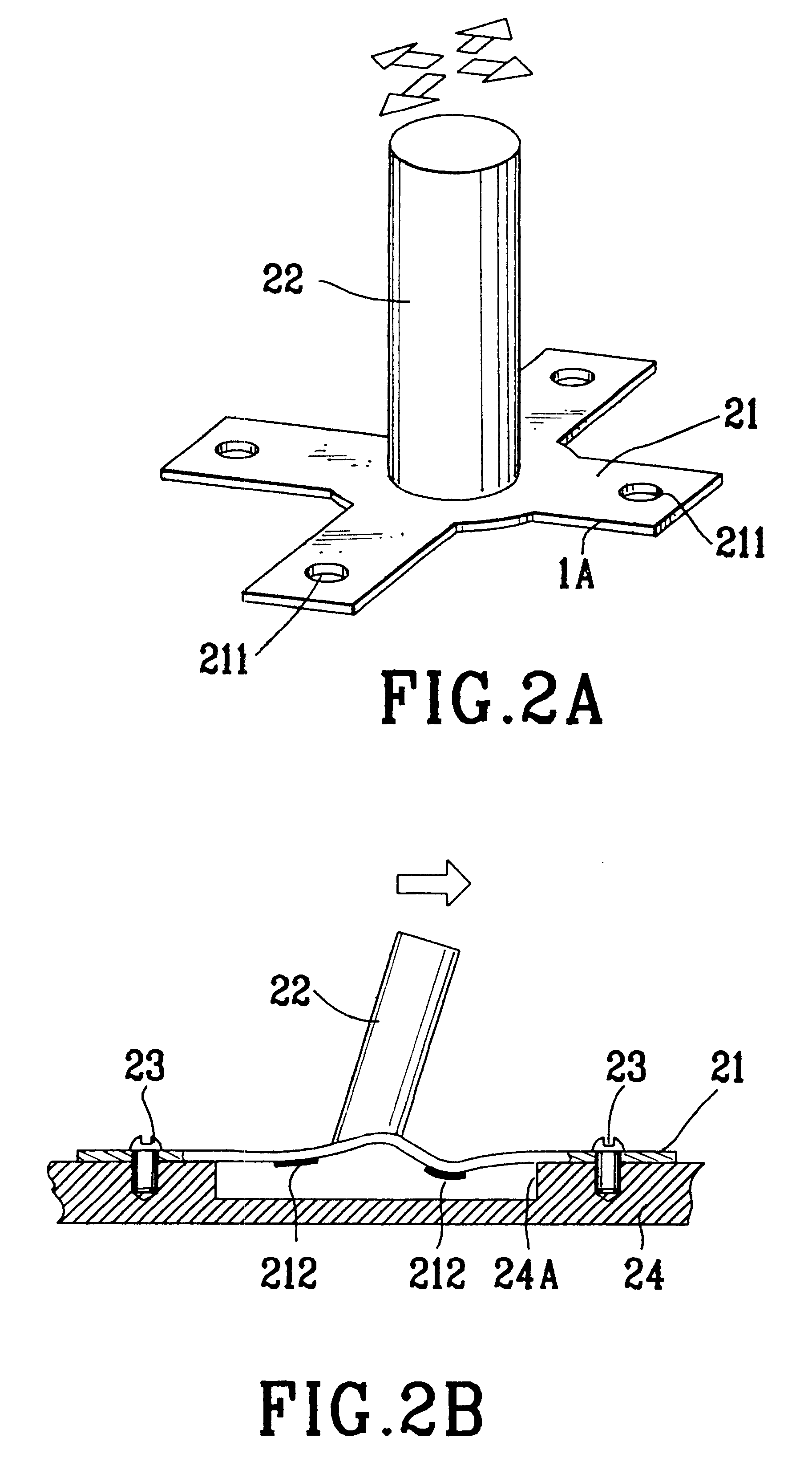
The pointing stick of the invention, as shown in FIG. 4, includes a substrate 41 and a stick 42. The stick 42 includes a circular column, i.e. a cylinder. Due to the cylinder form of the pointing stick, the sensors on the circular surface of the cylinder may be easily formed by a transfer print process, which is recited hereinafter.

Based on the assembly requirement, the substrate 41 may be in a corresponding suitable shape. We use a T-shaped substrate in the following as an embodiment. In order to assemble the substrate 41 to the keyboard baseplate (not shown), multiple of female screws 411 are provided. A plurality of sensors 422 are formed over the circular surface of the stick 42. As a preferred embodiment, three sensors 422 are used and each sensor 422 is spaced from another adjacent sensor by 120 degrees. The sensor 422 consists of two electrodes 4222, 4223, a strain gauge 4221 and a conductor 4224, which increases the conductivity. One end of the stick 42 is vertically dispose...


PUM


Abstract

A pointing stick used to control the cursor's movement on a display device is provided. The pointing stick includes a substrate and a stick. The stick has one end connected to the substrate and a portion of the stick is in form of cylinder. A plurality of sensors are disposed over the circular surface of the cylinder of the stick.

Description

The invention relates to a device for controlling the cursor movement on a display device.BACKGROUND OF INVENTIONThe traditional cursor controller, e.g. joystick or mouse, is not suitable for the notebook type computer system due to its size. As shown respectively in FIG. 1(A) and FIG. 1(B), a pointing stick 12 disposed on a keyboard 10 has been widely used in the notebook type computer due to its miniature structure. The state-of-art cursor controller device is disclosed in U.S. Pat. Nos. 5,521,596 and 5,640,178.The following introduces two types of state-of-art pointing stick. The pointing stick, disclosed in U.S. Pat. No. 5,640,178 and depicted in FIG. 2(A), FIG. 2(B), includes a substrate 21 and a stick 22 connected to the substrate 21. The substrate 21 is made of resilient material. According to the different designs, the substrate 21 may be in form of three or four blades structure. Four blades structure is shown in FIG. 2(A). At the end of each blade, one female screw 211 is ...

Claims


Application Information

Patent Timeline
IPC IPC(8): G01L5/22G06F1/16G06F3/033G06F3/0338
CPCG01L5/223G06F1/1616G06F3/0338G06F1/169Y10T74/20201
Inventor LIAO, PIN-CHIENLEE, TA YUAN
Owner BENQ CORP
Why Eureka
Try Eureka