Ordnance firing system

a firing system and ordnance technology, applied in the direction of electric fuzes, reactive armour, lighting and heating apparatus, etc., can solve the problems of increasing the fuel consumption of the device at all times during flight, avoiding the need for large and heavy batteries in aerospace and aeronautical devices, and reducing the safety of personnel

Inactive Publication Date: 2003-07-01
ENSIGN BICKFORD AEROSPACE & DEFENSE
View PDF53 Cites 84 Cited by
  • Summary
  • Abstract
  • Description
  • Claims
  • Application Information

AI Technical Summary

Problems solved by technology

The need in aerospace and aeronautical devices to provide such batteries, which are large and heavy, has been viewed as an unavoidable but significant burden.
The batteries occupy space which could go to other, more useful components of the device or to increased payload capacity and, for airborne devices, they also increase the fuel consumption of the device at all times during flight.

Method used


Image

  • Ordnance firing system
  • Ordnance firing system
  • Ordnance firing system

Examples


Embodiment Construction

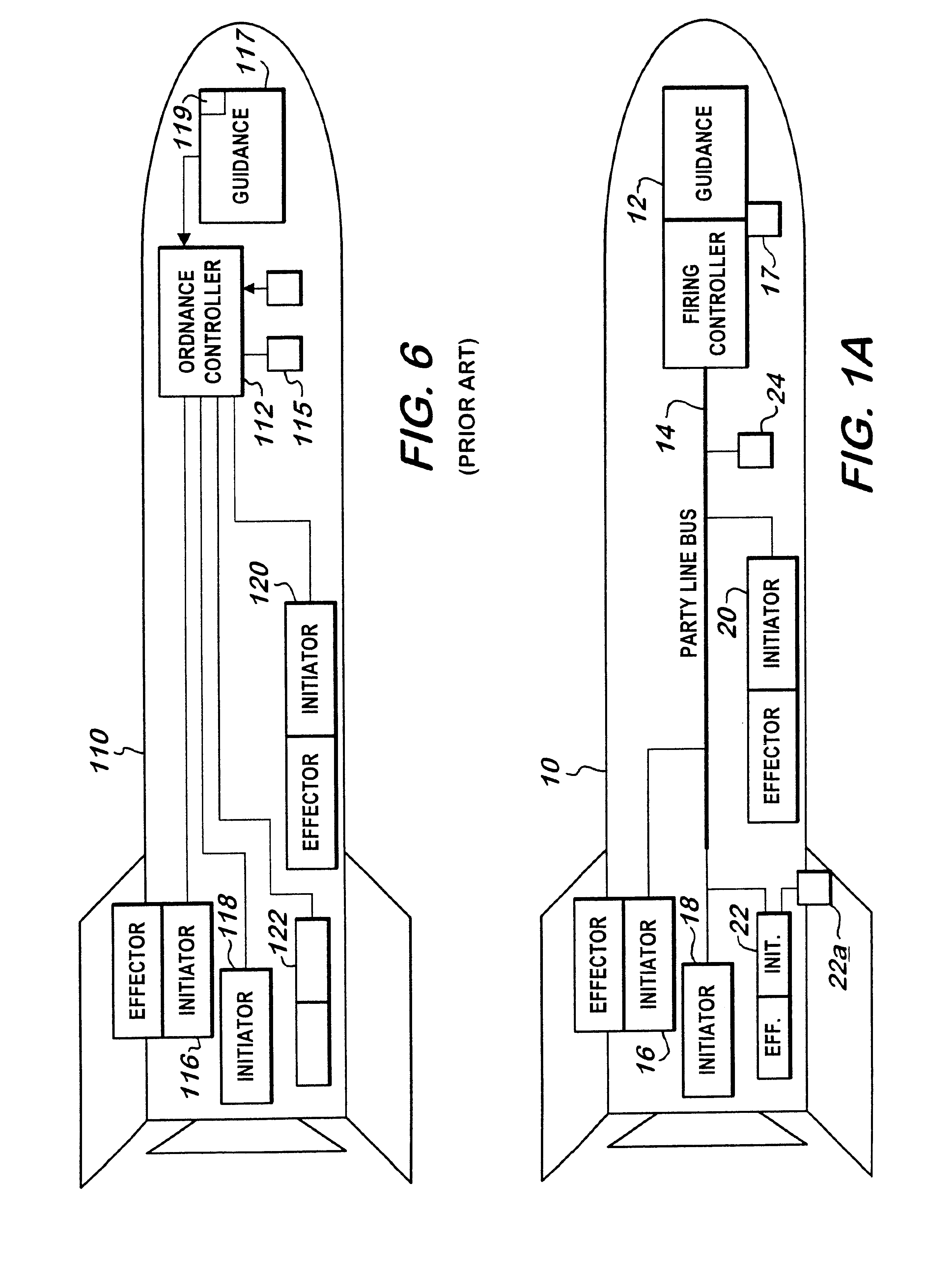
An ordnance firing system in accordance with the present invention may be utilized on numerous kinds of aeronautical and aerospace devices such as tactical missiles, cruise missiles, surface-to-air missiles, launch vehicles, satellites, etc. (as used herein, the term "aerospace devices" is meant to include aeronautical devices). In such devices, the ordnance system is used to initiate the function of various explosive or pyrotechnic effectors such as exploding bolts, bolt cutters, frangible joints, actuators, penetration charges, fragmentation charges, gas generators, inflators, motor igniters, through bulkhead initiators, explosive transfer lines, separation devices, destruct charges, pyrotechnically actuated valves, etc., referred to collectively herein as "reactive effectors" to include both explosive and pyrotechnic effectors. The ordnance firing system of this invention can also be used in land vehicles that utilize reactive effectors, e.g., in air bag deployment systems. One f...


PUM


Abstract

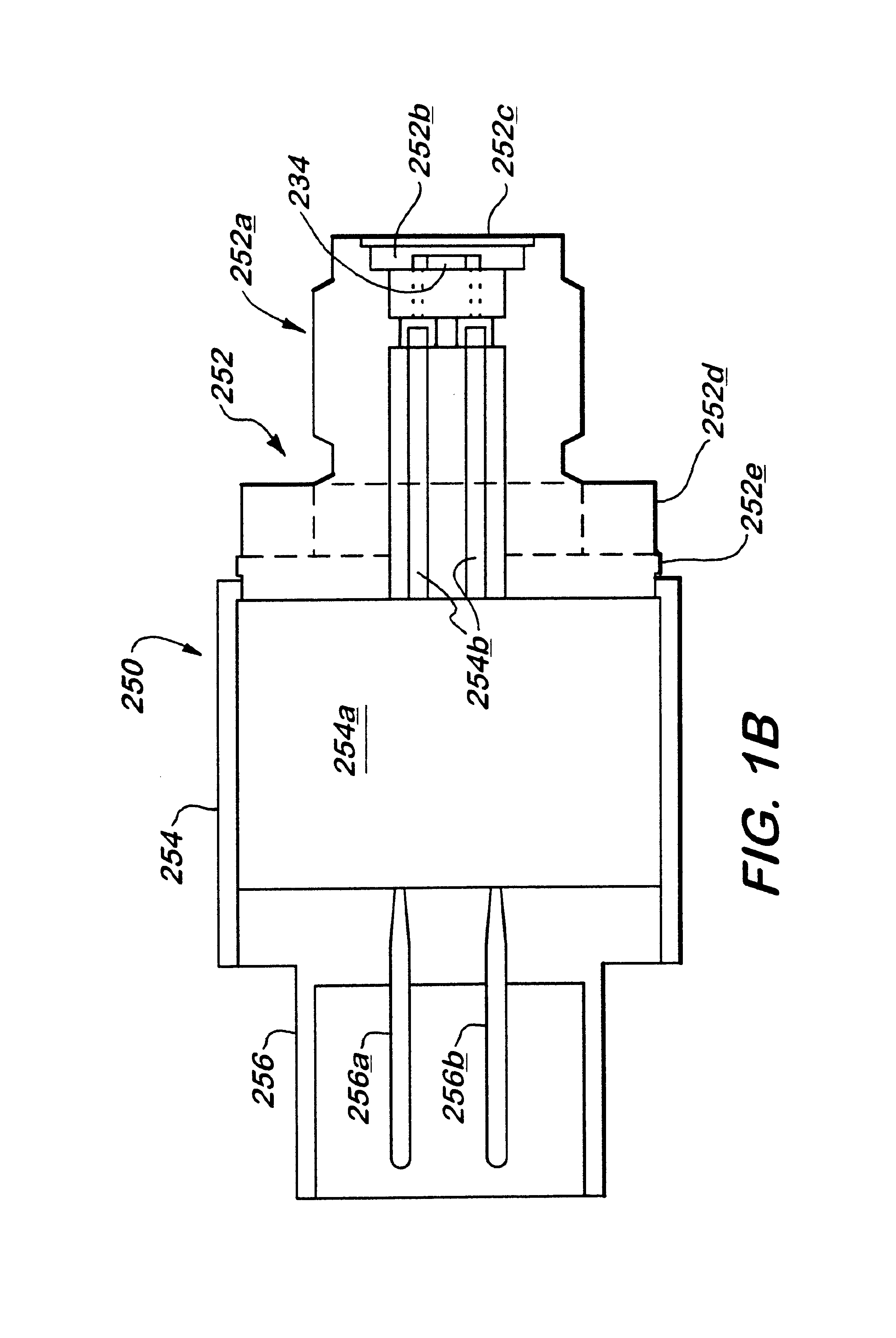
An ordnance system of the present invention may include or feature any one or more of: a control unit, one or more effectors (detonators, initiators, shaped charges and the like), and a two-, three- or four-wire communication bus between the control unit and the effectors; an addressable system in which all the effectors can be connected to the same communication bus and the control unit can issue coded signals on the bus addressed to a specific effector; inductive coupling between the effectors and the communication bus; and a multi-voltage level communication system in which communication signals are carried at a first voltage and arming signals are provided at a second, higher voltage. Other features may include two-way communication between effectors and the control unit and the de-centralization of firing control so that the control unit does not have exclusive control over whether the effectors function. As a result, the individual effectors possess decision-making ability and, for purposes of this invention, may be referred to as "intelligent" effectors. To participate in the decision-making process, effectors of this invention may be equipped with sensors or other diagnostic circuitry whose condition is checked for satisfactory output before functioning is permitted to occur.

Description

1. Field of the InventionThis invention relates to the initiation of explosive and pyrotechnic devices in aerospace and aeronautical devices and automotive vehicles.2. Related ArtExplosive and pyrotechnic devices such as explosive bolts, bolt cutters, separation fairings, actuators, engine igniters, etc., are used in aeronautical and aerospace applications to perform various functions such as the separation of one structure from another, the release of a structure from a stowed position to a deployed position, etc. They are also used in the safety systems of land vehicles such as automobiles, for the deployment of air bags. Such devices are typically coupled to electrically operated initiators which, in response to suitable electrical signals, initiate the devices. The initiation signals are provided by electronic control devices for controlling and coordinating the initiation of a plurality of initiators connected thereto. The combination of a control unit, a plurality of initiator...

Claims


Application Information

Patent Timeline
Patent Type & Authority Patents(United States)
IPC IPC(8): F42D1/05F42D1/00F42C15/40F42C15/00F41H5/007B60R21/26
CPCB60R21/017F41H5/007F42C15/40F42D1/05B60R2021/26029
Inventor BOUCHER, CRAIG J.MARSHALL, PAUL N.NOVOTNEY, DAVID B.
Owner ENSIGN BICKFORD AEROSPACE & DEFENSE
Why Eureka
Try Eureka