Self-deploying catheter assembly

a self-deploying, catheter technology, applied in the direction of catheters, dilators, infusion syringes, etc., can solve the problems of increased discomfort, increased catheter diameter, and increased risk of kinks in the lumen of a small diameter, so as to facilitate a low-profile state

Inactive Publication Date: 2003-07-08
APPL MEDICAL RESOURCES CORP
View PDF18 Cites 315 Cited by
  • Summary
  • Abstract
  • Description
  • Claims
  • Application Information

AI Technical Summary

Benefits of technology

, a self-deploying catheter assembly comprises an anchoring device mounted to a tube. A distal end of the anchoring device is held in a fixed position by a releasable suture while a proximal end is freely movable between a proximal position and a distal position defined by a stop on the tube. During insertion into a body cavity, the anchor automatically maintains a low-profile state with the ends spaced apart. Once fully inserted, the anchor self converts into a high-profile state when the tube is slightly withdrawn, bringing the ends closer together. The suture is disengaged to release the distal end of the anchor in order to facilitate a low-profile state for withdrawal of the assembly.

Problems solved by technology

A larger catheter diameter, however, increases discomfort.
While decreasing the diameter of the inflation lumen may contribute to a slightly smaller overall diameter of the catheter, an inflation lumen with a small diameter is more likely to develop kinks in the passageway, obstructing the flow of fluid necessary to inflate and deflate the balloon.
This greater "stack profile" increases discomfort.
Furthermore, particular body cavities can only accommodate a-certain length of catheter.
Therefore, limited room is available for the placement of ports on the shaft, which leads to a small overall area for drainage.
This smaller area contributes to excessive residual liquid remaining in the body cavity which may lead to infections and other complications.
Predilation, resulting in severe trauma to the patient, can occur if the deploying device, such as a balloon, is prematurely expanded in the narrow body conduit connected to the cavity.
The removal of conventional catheters is also problematic because manual manipulation is required.
The necessity for manual manipulation in conventional assemblies increases time, effort, expense and inconvenience in withdrawing a catheter.

Method used


Image

  • Self-deploying catheter assembly
  • Self-deploying catheter assembly
  • Self-deploying catheter assembly

Examples


Embodiment Construction

The invention and its various embodiments can now be better understood by turning to the following detailed description wherein illustrated embodiments are described. It is to be expressly understood that the illustrated embodiments are set forth as examples and not by way of limitations on the invention as ultimately defined in the claims.

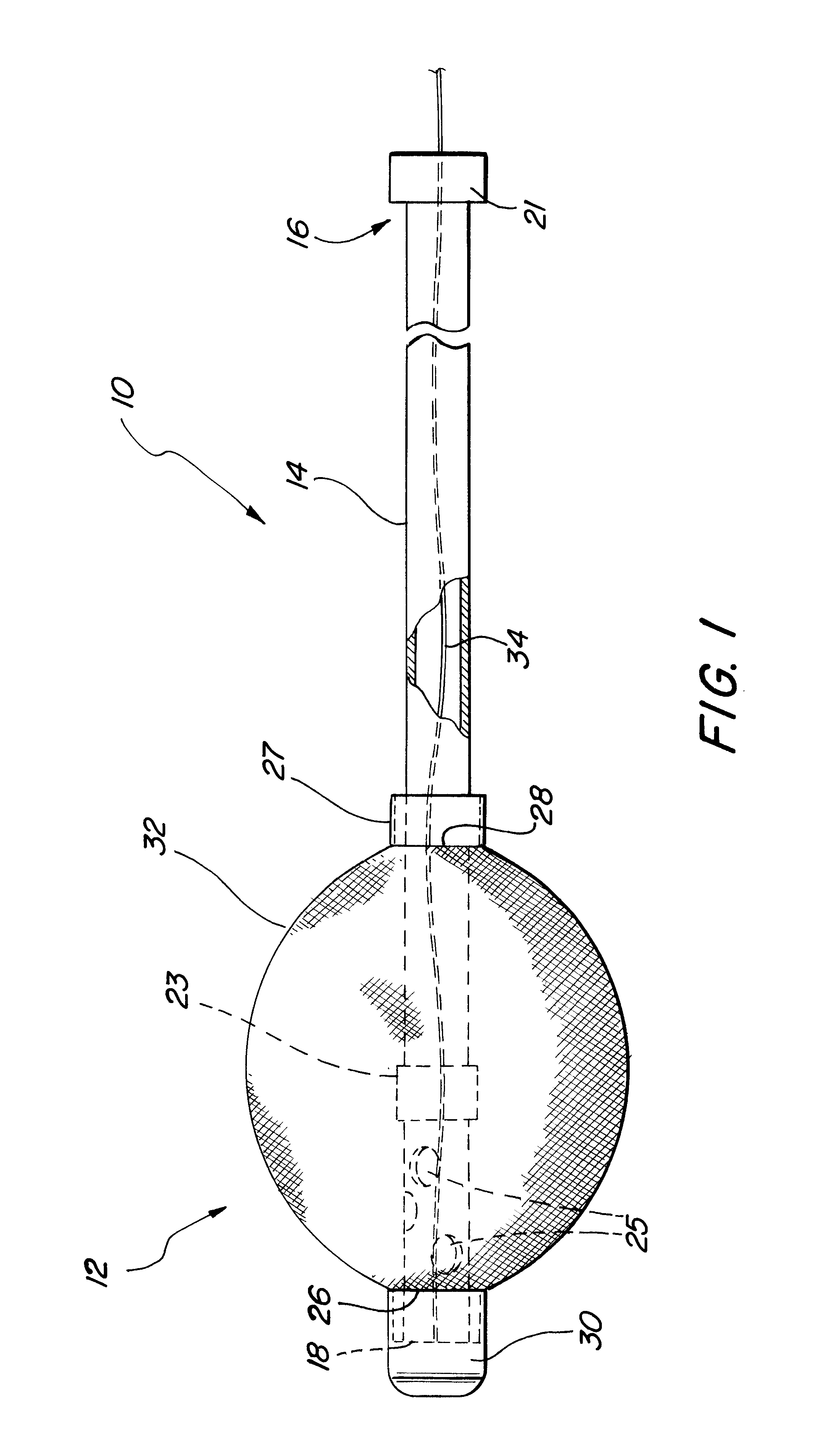
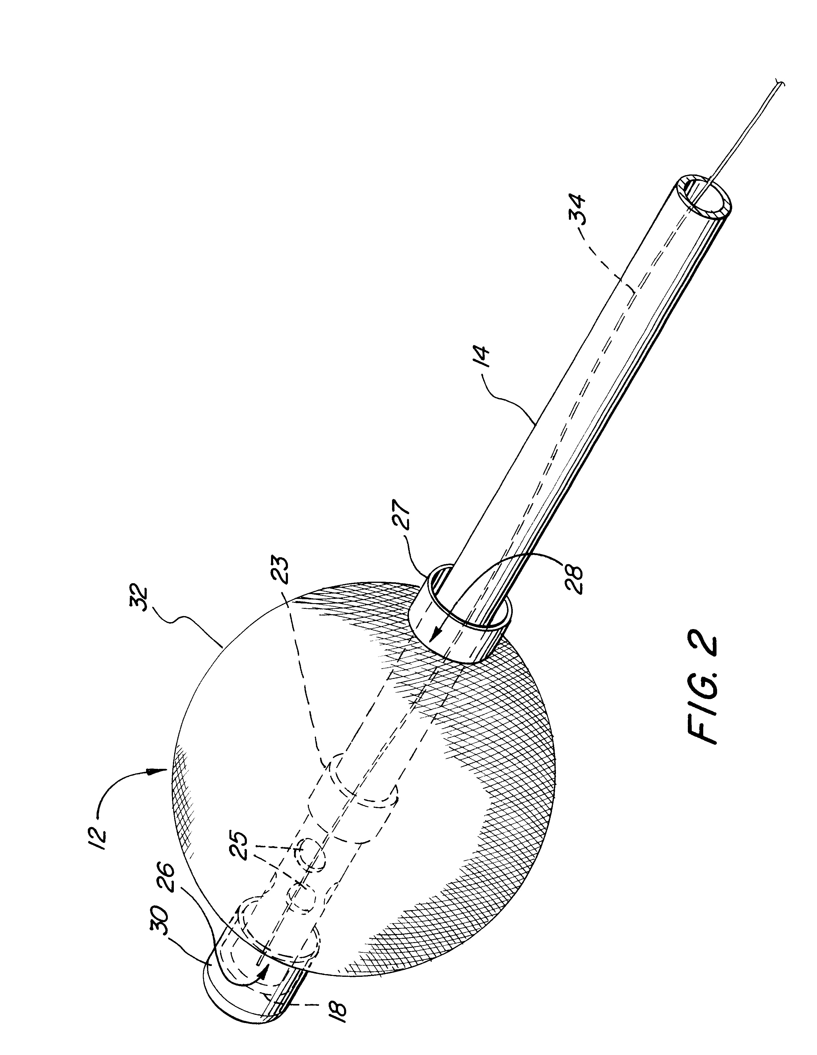
A first preferred embodiment of a catheter assembly is illustrated in FIG. 1 and designated generally by the reference numeral 10. This catheter assembly, or simply catheter 10, has a self-deploying tip, or anchor assembly 12, which can be advantageous in many catheter configurations. In FIGS. 1 and 2, the catheter 10 is adapted for urinary drainage where the anchor assembly 12 facilitates insertion of the catheter 10, automatic deployment of the tip 12, and simple removal of the catheter 10. Other catheters which can benefit from the self-deployment properties of the anchor assembly 12 include occlusion catheters, and generally any catheter in wh...


PUM


Abstract

A self-deploying catheter assembly comprises an anchoring device mounted to a tube. A distal end of the anchoring device is held in a fixed position by a releasable suture while a proximal end is freely movable between a proximal position and a distal position defined by a stop on the tube. During insertion into a body cavity, the anchor automatically maintains a low-profile state with the ends spaced apart. Once fully inserted, the anchor self converts into a high-profile state when the tube is slightly withdrawn, bringing the ends closer together. The suture is disengaged to release the distal end of the anchor in order to facilitate a low-profile state for withdrawal of the assembly.

Description

1. Field of the InventionThe present invention relates generally to medical and surgical devices, and more specifically to catheter assemblies.2. Description of Prior Art and Related InformationCatheter assemblies are generally inserted through body conduits to provide access to body cavities so as to enable medical procedures to be performed less invasively. In certain procedures, such as surgery or drainage, it is necessary for the catheter to be temporarily anchored in the body cavity to allow the desired procedure to be completed.Different mechanisms have been provided for the purpose of deploying a catheter within a body cavity in order to prevent withdrawal during a procedure. One example includes an inflatable balloon disposed on the tip of a catheter. Once the tip is within the body cavity, the balloon is inflated through an inflation lumen running through the shaft of the catheter. The presence of the inflation lumen, however, increases the necessary diameter of the shaft w...

Claims


Application Information

Patent Timeline
Patent Type & Authority Patents(United States)
IPC IPC(8): A61M25/04A61M25/02A61M25/10A61M25/00A61F2/958
CPCA61M25/04A61M25/10A61M25/0017A61M2025/0213
Inventor EWERS, RICHARD C.PRAVONG, BOUNDULAK, GARY R.
Owner APPL MEDICAL RESOURCES CORP
Why Eureka
Try Eureka