High-voltage interrupter device having combined vacuum and gas interruption

a technology of high-voltage interrupter and vacuum, which is applied in the direction of high-tension/heavy-dress switch, air-break switch, electrical apparatus, etc., can solve the problems of inability to modify the sequence for separating contacts, inability to obtain simultaneous or delayed separation of contacts with such a device, and insatiable sequences

Inactive Publication Date: 2003-07-15
ALSTOM TECH LTD
View PDF7 Cites 28 Cited by
  • Summary
  • Abstract
  • Description
  • Claims
  • Application Information

AI Technical Summary

Benefits of technology

An object of the invention is to remedy the drawbacks or limitations of the prior art, by providing a hybrid interrupter device for high or medium voltage that is relatively compact and longlasting, and that when operating with a single drive member, i.e. with a control mechanism connected to a single drive rod, enables the interrupter contact separation sequence to be adjusted.
displacement means connected to the connection means and to the drive rod for displacing them so as to separate the second and fourth contacts from the first and third contacts respectively, said displacement means comprising dead-stroke link means connecting the connection means to the rod, the link means making it possible to displace the rod over a determined dead stroke while also acting on the connection means to keep the vacuum interrupter closed during this displacement.
a first portion of said return means is subjected to a thrust from the first resilient means which makes it possible to displace said portion over said dead stroke relative to the connection means, a second portion of said return means being constrained to move in translation with the rod.
FIG. 4 is a diagram showing the principle of a hybrid interrupter device of the invention that is identical to the device shown in FIG. 1 except that the gas interrupter contacts are organized so that their separation occurs a short time before the separation of the contacts of the vacuum interrupter;

Problems solved by technology

Unfortunately, such a sequence is not satisfactory if the high-voltage hybrid device associates a gas interrupter designed for a standardized high voltage higher than 72.5 kV with a vacuum interrupter designed for a standardized medium voltage lower than 52 kV.
Unfortunately, the vacuum interrupter is designed to withstand only a recovered voltage that remains within medium voltage limits.
The general structure of the device described in that U.S. Pat. No. 3,038,980 does not make it possible to modify the sequence for separating the contacts.
In particular, it is not possible with such a device to obtain simultaneous or delayed separation of the contacts of the vacuum interrupter relative to the separation of the contacts of the gas interrupter.
However, that device presents certain drawbacks from a mechanical point of view.
Secondly, the motion of the drive rod of the gas interrupter is transmitted towards the vacuum interrupter by a connecting rod having an axis that is oblique relative to the axis of translation of the moving contact of the vacuum interrupter.
That results in significant transverse stresses on the vacuum interrupter, thereby limiting its mechanical endurance.
However, in that device, the separating movement of the contacts of the vacuum interrupter is under the control of the drive rod of the gas interrupter, so the contacts of the vacuum interrupter can be separated only once the contacts of the gas interrupter have been opened.
Obviously, with that device, it is not possible to produce simultaneous or slightly delayed separation of the contacts of the vacuum interrupter relative to the separation of the contacts of the gas interrupter.

Method used


Image

  • High-voltage interrupter device having combined vacuum and gas interruption
  • High-voltage interrupter device having combined vacuum and gas interruption
  • High-voltage interrupter device having combined vacuum and gas interruption

Examples


Embodiment Construction

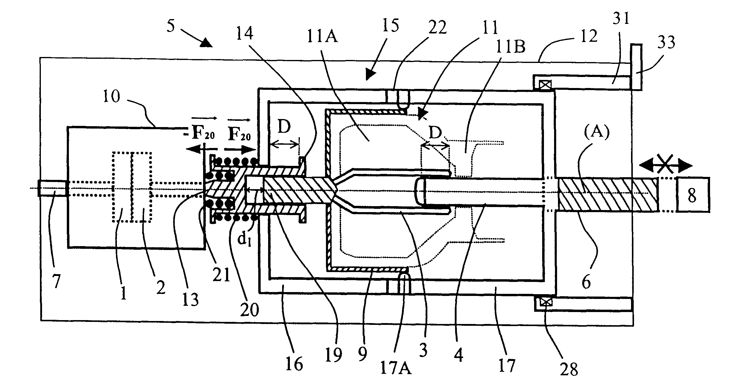
The high-voltage hybrid interrupter device 5 shown in FIG. 1 is substantially circularly symmetrical about an axis A. It includes a vacuum interrupter 10 enclosing a first pair of arcing contacts 1 and 2. A first contact 1 is fixed and is connected permanently to an end feedthrough 7 of the device 5. A second contact 2 is mounted to move along the axis A. The device also includes a gas interrupter 11 that is electrically connected in series with the vacuum interrupter. The gas interrupter contains a second pair of arcing contacts, constituted by a third contact 3 and by a fourth contact 4. The third contact 3 is fixed in the casing 12 by means of holding means shown in FIGS. 8 and 9. The fourth contact 4 is mounted to move along the axis A and is secured to a drive rod 6 that is connected to the control mechanism 8 for controlling the device 5. The two interrupters 10 and 11 are disposed in a common casing filled with a dielectric gas.

In the embodiment shown, the moving contact 4 is...


PUM


Abstract

A hybrid interrupter device includes a casing filled with a dielectric gas; a vacuum interrupter having a first arcing contact which is fixed and a second arcing contact which moves in translation in the axial direction of the casing; a force exertion device for exerting a force on the second contact while the vacuum interrupter is allowing current to pass; a gas interrupter having a third arcing contact which is fixed and a fourth arcing contact which moves in translation; and a drive rod connected to the fourth contact. The device further includes a connection device electrically interconnecting the second and third contacts, and capable of being moved in translation together with the second contact; and a displacement mechanism connected to the connection device and to the rod for displacing them so as to separate the second and fourth contacts from the first and third contacts, respectively.

Description

The invention relates to an interrupter device of the hybrid type for high or medium voltage. The term "hybrid" applies to interruption which is of the combined type in which two different interruption techniques are caused to co-operate. The term "hybrid" is used in particular to designate an interrupter device that comprises both a vacuum interrupter containing a first pair of arcing contacts, and also a gas interrupter containing a second pair of arcing contacts.A device of this type is known from U.S. Pat. No. 3,038,980. It comprises a casing filled with a dielectric gas and having a longitudinal axis. The two interrupters are connected electrically in series and are disposed inside the casing, while the control mechanism for controlling the device is disposed outside the casing. The mechanism for actuating the contacts of the two interrupters is relatively simple in that one of the two contacts of the gas interrupter is secured to a moving contact which is adjacent to it in the...

Claims


Application Information

Patent Timeline
Patent Type & Authority Patents(United States)
IPC IPC(8): H01H33/14H01H33/04H01H33/66H01H33/42
CPCH01H33/143H01H33/6661H01H2033/566
Inventor PERRET, MICHELDUFOURNET, DENIS
Owner ALSTOM TECH LTD
Why Eureka
Try Eureka