Electrical starting, generation, conversion and distribution system architecture for a more electric vehicle

a technology for electric vehicles and distribution systems, applied in emergency power supply arrangements, energy-efficient board measures, electric devices, etc., can solve the problem of higher criticality and availability of electrical power

Inactive Publication Date: 2006-03-23
HONEYWELL INT INC
View PDF22 Cites 193 Cited by
  • Summary
  • Abstract
  • Description
  • Claims
  • Application Information

AI Technical Summary

Benefits of technology

[0007] In one aspect, the present invention is a system for distributing electrical power, comprising: a first high voltage AC power distributing unit including a first high voltage AC bus, which is selectively connected to a first high voltage AC generator, and a first start bus; a second high voltage AC power distributing unit including a second high voltage AC bus, which is selectively connected to a second high voltage AC generator, and a second bus; a first high voltage DC power distributing unit including a first rectifier unit, a first high voltage DC bus, and a first motor controller, the first rectifier being selectively connected to the first high voltage AC bus of the first high voltage AC power distributing unit to convert high voltage AC power to high voltage DC power, which is provided to the first high voltage DC bus; and a second high voltage DC power distributing unit including a second rectifier unit, a second high voltage DC bus, and a second motor controller, the second rectifier being selectively connected to the second high voltage AC bus of the second high voltage AC power distributing unit to convert high voltage AC power to high voltage DC power, which is provided to the second HVDC bus. The first high voltage bus is selectively connectable to the second high voltage DC bus and the first high voltage AC bus is selectively connectable to the second high voltage AC bus. The system provides redundancy for both high voltage AC power distribution and high voltage DC power distribution.
[0008] In another aspect, the present invention is a system for distributing electrical power, comprising: a first high voltage AC power distributing unit including a first high voltage AC bus, which is selectively connected to a first high voltage AC generator; a second high voltage AC power distributing unit including a second high voltage AC bus, which is selectively connected to a second high voltage AC generator; a first low voltage AC power distributing unit including a first low voltage AC bus and a first AC essential bus, which is selectively connectable to a first emergency generator and selectively connectable to the first low voltage AC bus, wherein the first low voltage AC power distributing unit is selectively connectable to the first high voltage AC bus to convert high voltage AC power to low voltage AC power, which is output to the first low voltage AC bus; a second low voltage AC power distributing unit including a second low voltage AC bus and a second AC essential bus, which is selectively connectable to a second emergency generator and selectively connectable to the second low voltage AC bus, wherein the second low voltage AC power distributing unit is selectively connectable to the second high voltage AC bus to convert high voltage AC power to low voltage AC power, which is output to the second low voltage AC bus; a first low voltage DC power distributing unit including a first low voltage DC essential bus and a first low voltage DC main bus; and a second low voltage DC power distributing unit including a second low voltage DC essential bus and a second low voltage DC main bus. The first high voltage AC bus is selectively connectable to the second high voltage AC bus, the first low voltage AC bus is selectively connectable to the second low voltage AC bus, the first AC essential bus is selectively connectable to the second AC essential bus, the first low voltage DC essential bus is selectively connectable to the second low voltage DC essential bus, and the first low voltage DC main bus is selectively connectable to the second low voltage DC main bus, thereby providing redundancy of both low voltage AC power distribution and low voltage DC power distribution.

Problems solved by technology

Another challenge for the MEV electrical system results from the higher criticality and availability of electrical power required by the systems and services that it supports.

Method used


Image

  • Electrical starting, generation, conversion and distribution system architecture for a more electric vehicle
  • Electrical starting, generation, conversion and distribution system architecture for a more electric vehicle
  • Electrical starting, generation, conversion and distribution system architecture for a more electric vehicle

Examples


Embodiment Construction

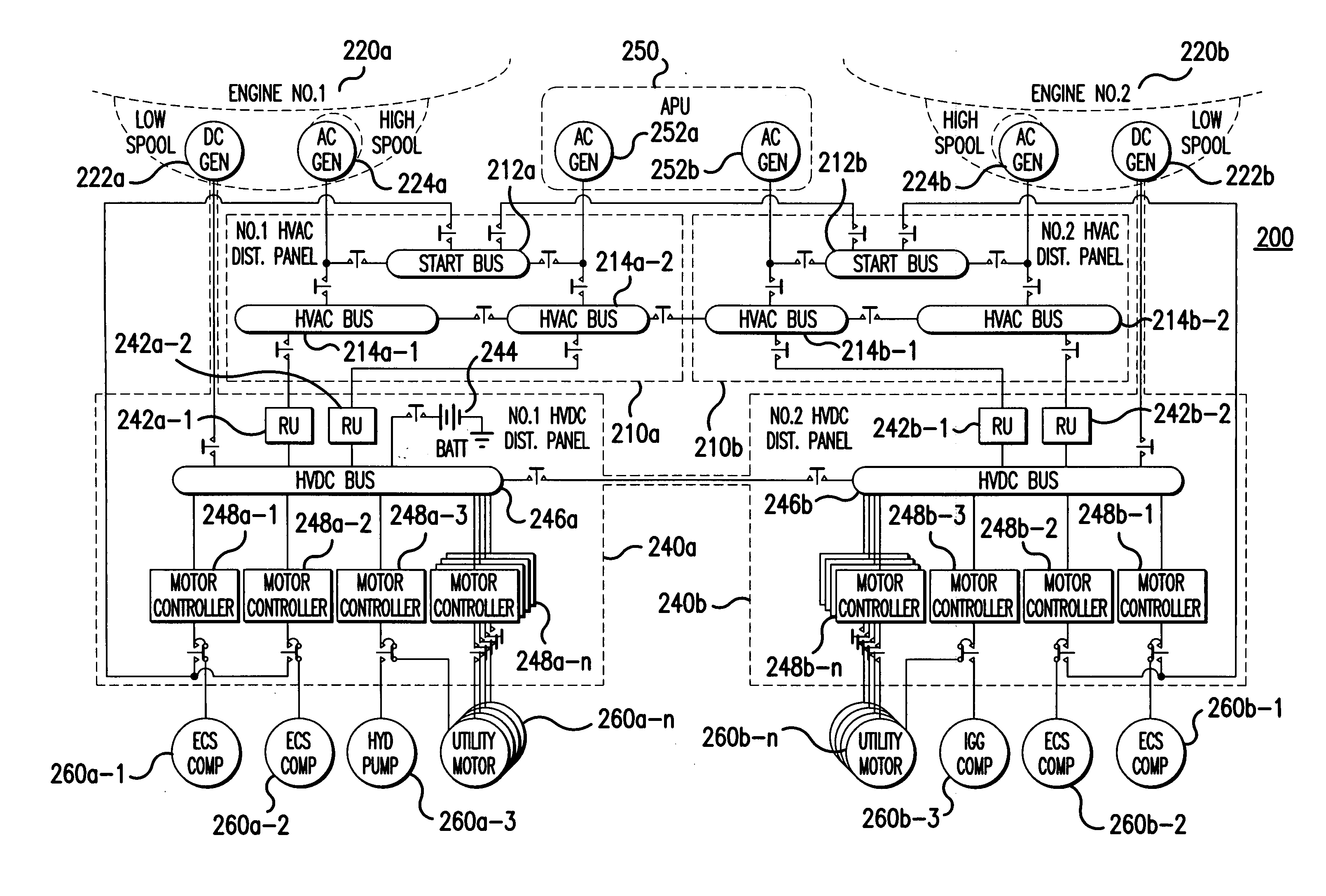
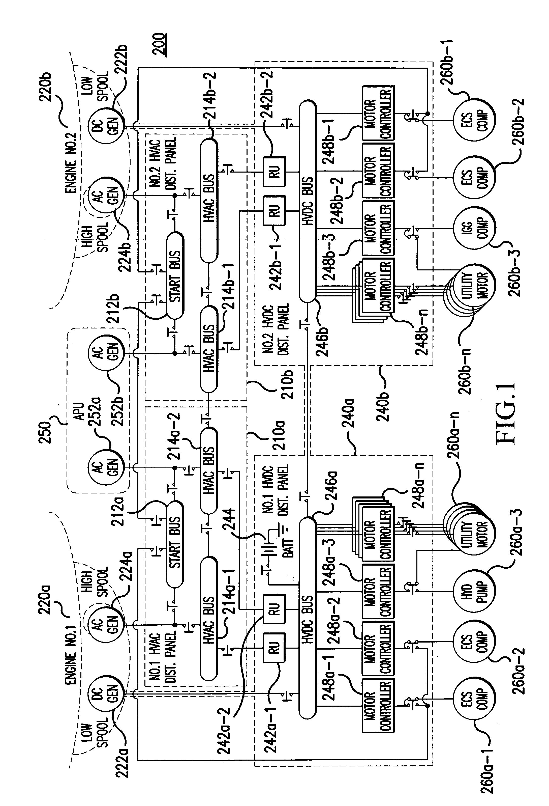
[0012] In one aspect, a disclosed embodiment is a redundant, symmetrical system for electrical engine starting, power generation, conversion and distribution, maximizing reconfiguration at primary and secondary bus levels without single string paths who's failure to function can affect function, operation and dispatch. Although aspects of the detailed description provided herein are specific to implementation in a more electric aircraft (MEA), it should be recognized that principles of the present invention are not limited to such an application, and can be applied to other vehicles types.

[0013]FIG. 1 illustrates an architecture for high voltage electrical starting, generation, and distribution in an MEV in accordance to an embodiment of the present invention. In the embodiment of FIG. 1, a high voltage electrical power system 200 includes: first and second engines 220a, 220b; first and second high voltage AC (HVAC) distribution units 210a, 210b; first and second high voltage DC (H...


PUM


Abstract

A system (200) for distributing electrical power, includes: a first high voltage AC power distributing unit (210a) including a first high voltage AC bus (214a-1, 214a-2), which is selectively connected to a first high voltage AC generator (224a), and a first start bus (212a); a second high voltage AC power distributing unit (210b) including a second high voltage AC bus (214b-1, 214b-2), which is selectively connected to a second high voltage AC generator (224b), and a second start bus (212b); a first high voltage DC power distributing unit (240a) including, a first high voltage DC bus (246a), and a second high voltage DC power distributing unit (240b) including a second high voltage DC bus (246b). The first high voltage AC bus (214a-1, 214a-2) is selectively connectable to the second high voltage AC bus (214b-1, 214b-2), such that the system (200) provides redundancy for high voltage power distribution.

Description

RELATED APPLICATIONS [0001] The present application claims priority under 35 U.S.C. §119(e) of provisional patent application No. 60 / 603,631 filed Aug. 24, 2004, which is hereby incorporated by reference in its entirety. The present application is related to: a co-pending U.S. application Ser. No. 11 / 199,151, filed on Aug. 4, 2005, entitled “Electrical Energy Management System On A More Electric Vehicle,” a co-pending U.S. application Ser. No. 11 / 196,323, filed on Aug. 9, 2005, entitled “Electrical Power Distribution System And Method With Active Load Control”, and a co-pending U.S. application filed on Aug. 18, 2005, entitled “Method and System for Coordinating Engine Operation with Electrical Power Extraction in a More Electric Vehicle,” which are hereby incorporated by reference in their entirety. FIELD OF THE INVENTION [0002] The present invention relates to electrical power distribution, and more particularly to a redundant, symmetrical system for electrical engine starting, po...

Claims


Application Information

Patent Timeline
Patent Type & Authority Applications(United States)
IPC IPC(8): B60L1/00H02J1/00
CPCB64D2221/00Y02T50/54Y02T50/545H02J4/00H02J2310/44Y02T50/50
Inventor MICHALKO, RODNEY G.
Owner HONEYWELL INT INC
Why Eureka
Try Eureka