
Method and device for the production of rolls of web material without a winding core

a technology of winding core and web material, which is applied in the direction of thin material processing, transportation and packaging, filament handling, etc., can solve the problem of no system for applying vacuum to the spindle, and achieve the effect of convenient high-speed production, efficient and fas

Inactive Publication Date: 2003-07-22
FABIO PERINI SPA
View PDF22 Cites 102 Cited by
  • Summary
  • Abstract
  • Description
  • Claims
  • Application Information

AI Technical Summary

Benefits of technology

One object of the present invention is to provide a method and a surface winding device which allow the production of rolls or logs without a tubular core, in which the initial step for causing the free leading edge of web material to adhere to the winding spindle is efficient, fast and reliable and is suitable for high production speeds.
A further object of the present invention is to provide a method and a device of the abovementioned type, in which the step involving extraction of the spindle from the finished roll or log is easy and is not affected by the procedures used to start winding.
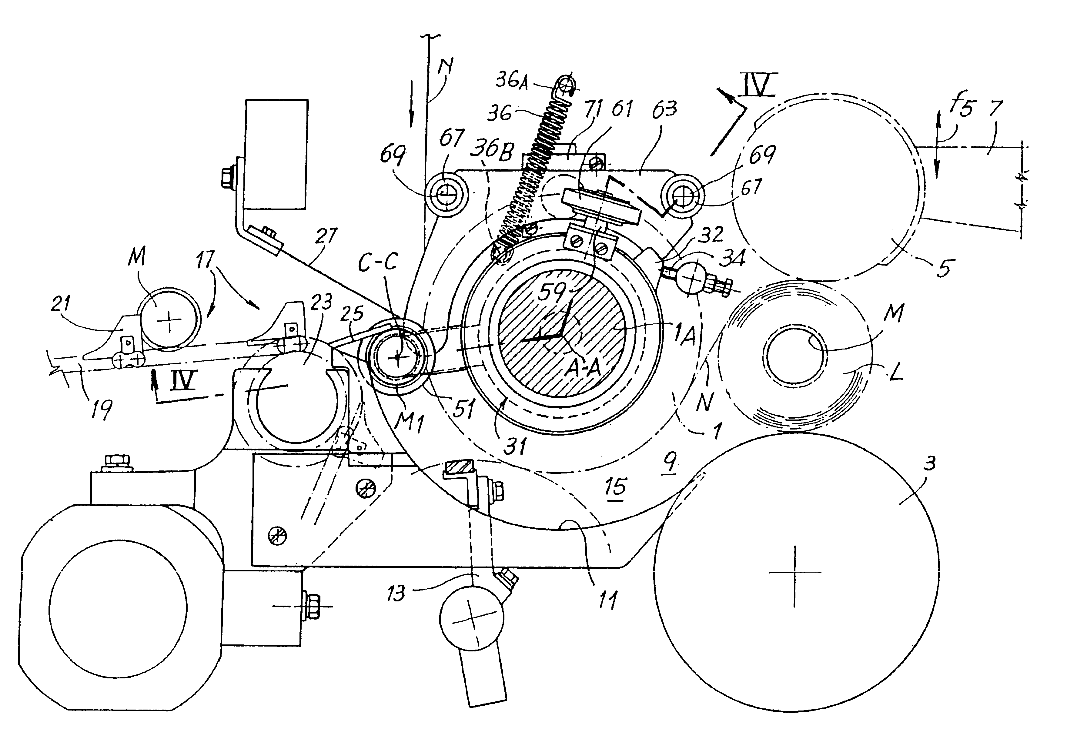
These and further objects and advantages, which will become clear to persons skilled in the art from a reading of the text below, are obtained by means of a surface rewinding machine of the type comprising a winding cradle for sequentially forming rolls of web material, an insertion device for inserting the winding spindles into the winding cradle and an insertion path for introducing the winding spindles into the cradle. According to the invention, a rewinding machine of this type is provided with a suction system cooperating with the spindles along at least one portion of the insertion path so as to produce a vacuum inside the spindles which have a wall which is permeable to air and typically provided with a series of holes which could also have microscopic dimensions. The suction system follows the movement of the spindles over at least part of the insertion path. This enables high production speeds to be achieved.
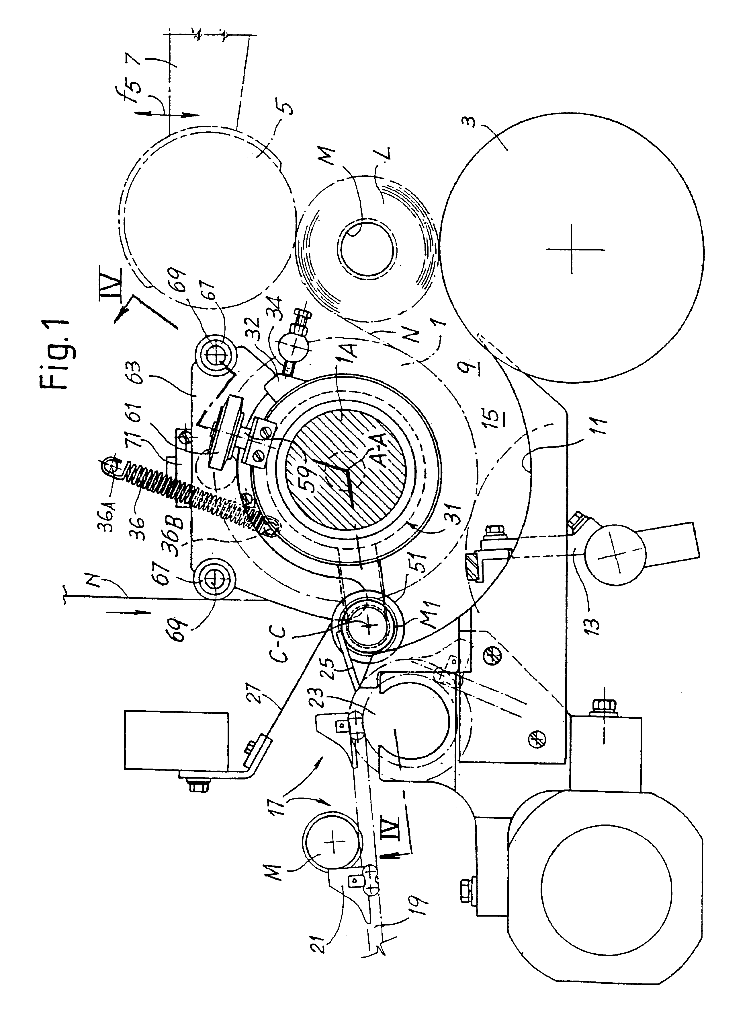
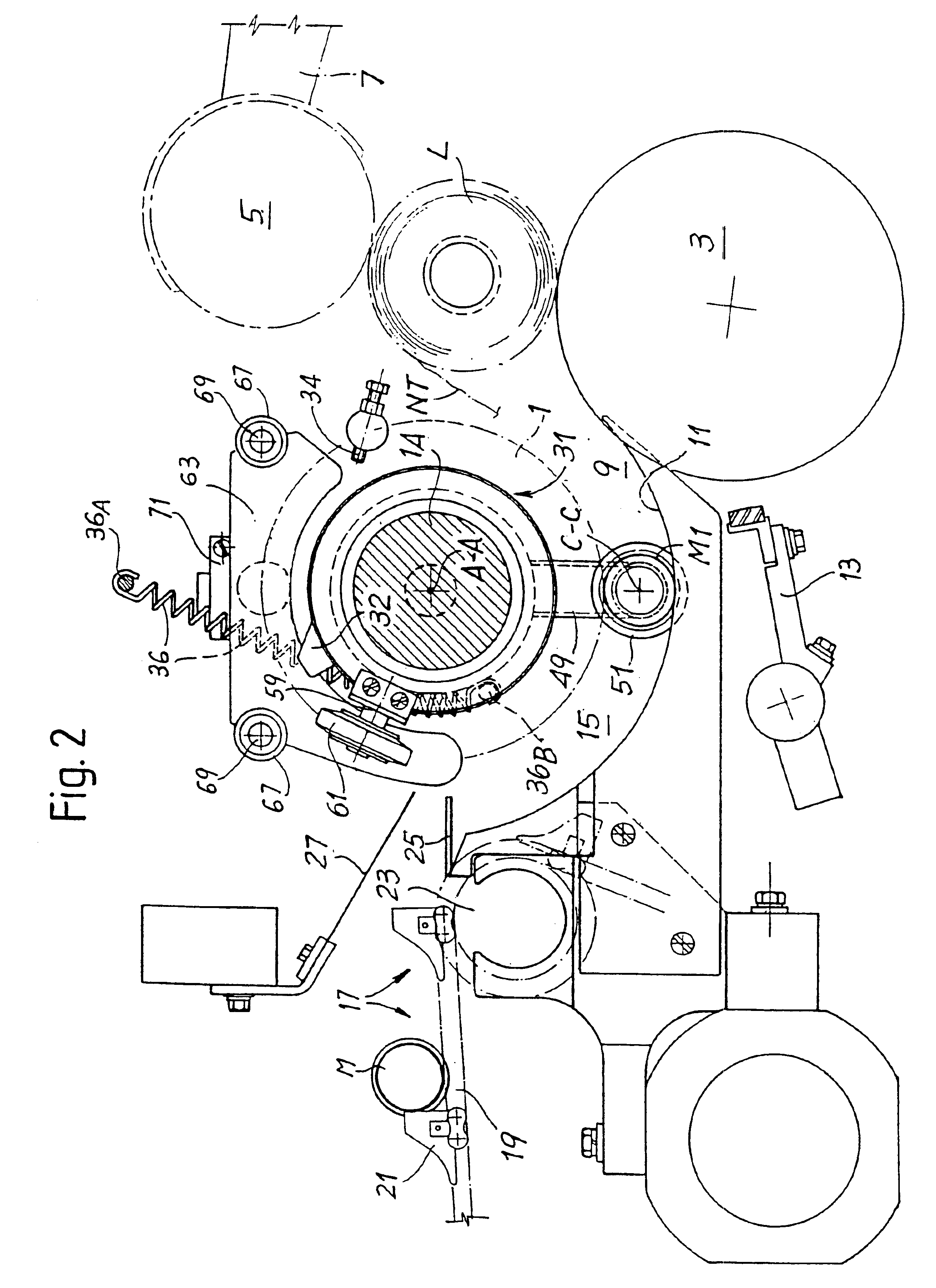
The oscillating movement of the unit supporting the nozzle or nozzles about the axis of the first winding roller may be obtained, for example, by means of a system comprising a motor and a pinion and crown-wheel transmission system. However, according to a particularly advantageous embodiment of the invention, the rotating unit may support a small shaft which has an axis perpendicular to the axis of rotation of the first winding roller and on which a wheel is mounted in an idle manner. Said wheel is made to roll over a surface not rotating with respect to the axis of rotation of the first winding roller and over an annular surface of the first winding roller, perpendicular to its axis. In this way, as will be clarified more fully below, the unit supporting the nozzle or nozzles moves at a speed equal to the speed of movement of the individual spindles along the insertion path. This solution is particularly advantageous because it is mechanically simple and can be easily synchronized with the spindle movement, without the need for special measures.

Problems solved by technology

One of the difficulties of these machines and the associated winding methods relates to the first winding phase when the leading edge of the web material must be made to adhere to the spindle so as to start formation of the turns.
However, no system for applying the vacuum to the spindle is described.

Method used


Image

  • Method and device for the production of rolls of web material without a winding core
  • Method and device for the production of rolls of web material without a winding core
  • Method and device for the production of rolls of web material without a winding core

Examples


Embodiment Construction

The invention is illustrated below with reference to application to a surface rewinding machine of the type described in WO-A-9421545. Further details regarding the machine and the winding method may be found in said international publication. Those features necessary for understanding the present invention will be described below.

The rewinding machine comprises a winding cradle formed by three winding rollers indicated by 1, 3 and 5. The third winding roller 5 is mounted on an oscillating arm 7 which allows its movement in the direction of the arrow f5 so as to allow an increase in the diameter of the roll or log L being formed. As is known per se, the first and the second winding roller 1, 3 form a nip 9 through which the winding spindle passes in the manner described below.

The nip 9 has, arranged upstream of it, a curved rolling surface 11 defined by a comb-like structure through which a mechanism for interrupting or cutting the web material, denoted by 13, passes. The curved rol...


PUM

PropertyMeasurementUnit
Adhesion strengthaaaaaaaaaa
Shapeaaaaaaaaaa
Dimensionaaaaaaaaaa

Abstract

A surface rewinding machine for the production of rolls of wound web material is described. The machine comprises: a winding cradle (1, 3, 5) for winding the web material and sequentially forming rolls (R) of wound web material; an insertion device (25) for inserting sequentially, into said winding cradle, winding spindles (M1; M) on which the rolls are formed; an insertion path for the spindles inside the winding cradle. A suction system (51) which follows the spindles along at least one portion of the insertion path so as to produce a vacuum inside the spindles is also envisaged.

Description

The present invention relates to a rewinding machine for the production of rolls of web material, for example rolls of so-called tissue paper, so as to obtain small rolls of toilet paper, all-purpose drying paper and the like.The present invention also relates to a method for the production of rolls without a central winding core.In order to produce rolls or "logs" of web material, so-called rewinding machines are commonly used, in which machines a predetermined length of web material is wound onto a tubular winding core normally made of cardboard. These rolls or logs are then cut into a plurality of smaller-size rolls intended for sale. A tubular winding core section remains inside each small roll.The winding machines of this type are divided into two categories depending on the manner in which the winding movement is provided. In a first type of rewinding machine, known as a central spindle rewinding machine, a spindle supported on support elements between a pair of side walls rec...

Claims


Application Information

Patent Timeline
IPC IPC(8): B65H19/22B65H19/28
CPCB65H19/2276B65H19/28B65H2301/41426B65H2301/41812B65H2406/30B65H2408/235
Inventor BIAGIOTTI, GUGLIELMO
Owner FABIO PERINI SPA
Learn More