Belt for continuously variable transmission

a technology of continuously variable transmission and belt, which is applied in the direction of driving belts, belts/chains/gearrings, v-belts, etc., can solve the problems of difficult to ensure, pulleys, etc., and achieve the effect of reducing the v-face height of metal elements and reducing the uneven wear of metal elements

Inactive Publication Date: 2003-07-29
HONDA MOTOR CO LTD
View PDF10 Cites 17 Cited by
  • Summary
  • Abstract
  • Description
  • Claims
  • Application Information

AI Technical Summary

Benefits of technology

The present invention has been accomplished with the above circumstance in view, and it is an object of the present invention to prevent the V-face from being inclined due to the load from the pulley to suppress the uneven wearing of the metal element and the pulley, while decreasing the V-face height of the metal element.
With the above arrangement, the height Hs of the upper non-contact portion of the V-face is set larger than the height Hs" of the lower non-contact portion of the V-face. Therefore, even if the V-face height Hv is decreased to decrease the pitching moment on the metal element due to the load applied to the V-face, the V-face can be prevented from inclination due to the load to decrease the parallelism, thereby preventing the uneven wearing of the V-face of the metal element and the V-groove of the pulley.
With the above arrangement, the ratio of the height Hs of the upper non-contact portion of the V-face to the height Hv of the V-face is set in the range of 0.149.ltoreq.Hs / Hv.ltoreq.0.258. Therefore, even if the V-face height Hv is decreased to decrease the pitching moment on the metal element due to the load applied to the V-face, the V-face can be prevented from inclination due to the load to decrease the parallelism, thereby preventing the uneven wearing of the V-face of the metal element and the V-groove of the pulley.
Therefore, even if the V-face height Hv is decreased to decrease the pitching moment on the metal element due to the load applied to the V-face, the V-face can be prevented from inclining due to the load to decrease the parallelism, thereby preventing the uneven wearing of the V-face of the metal element and the V-groove of the pulley.
With the above arrangement, a required amount of oil can be retained between the V-face of the metal element and the V-groove of the pulley, and an extra amount of oil can be discharged promptly, thereby stabilizing the coefficient of friction between the V-face and the V-groove.

Problems solved by technology

A belt for the continuously variable transmission suffers from the following problem: When left and right V-faces of the metal element receive an axial load from the V-grooves of the pulley, if the V-faces of the metal element are moved in an inclined manner rather than in parallel by the load, one end of the V-face is brought vertically into strong contact with the V-groove and as a result, the other end is lifted from the V-groove of the pulley, whereby an uneven wearing occurs in the metal element and the pulley.
However, if the V-face height Hv' is decreased, the shape of a recess 46' in the metal element 32' cannot be determined appropriately, and it is difficult to ensure that the sum total of moments applied to the saddle face 44' of the metal element is 0 (zero).

Method used


Image

  • Belt for continuously variable transmission
  • Belt for continuously variable transmission
  • Belt for continuously variable transmission

Examples


Embodiment Construction

The mode for carrying out the present invention will now be described by way of embodiments of the present invention shown in the accompanying drawings.

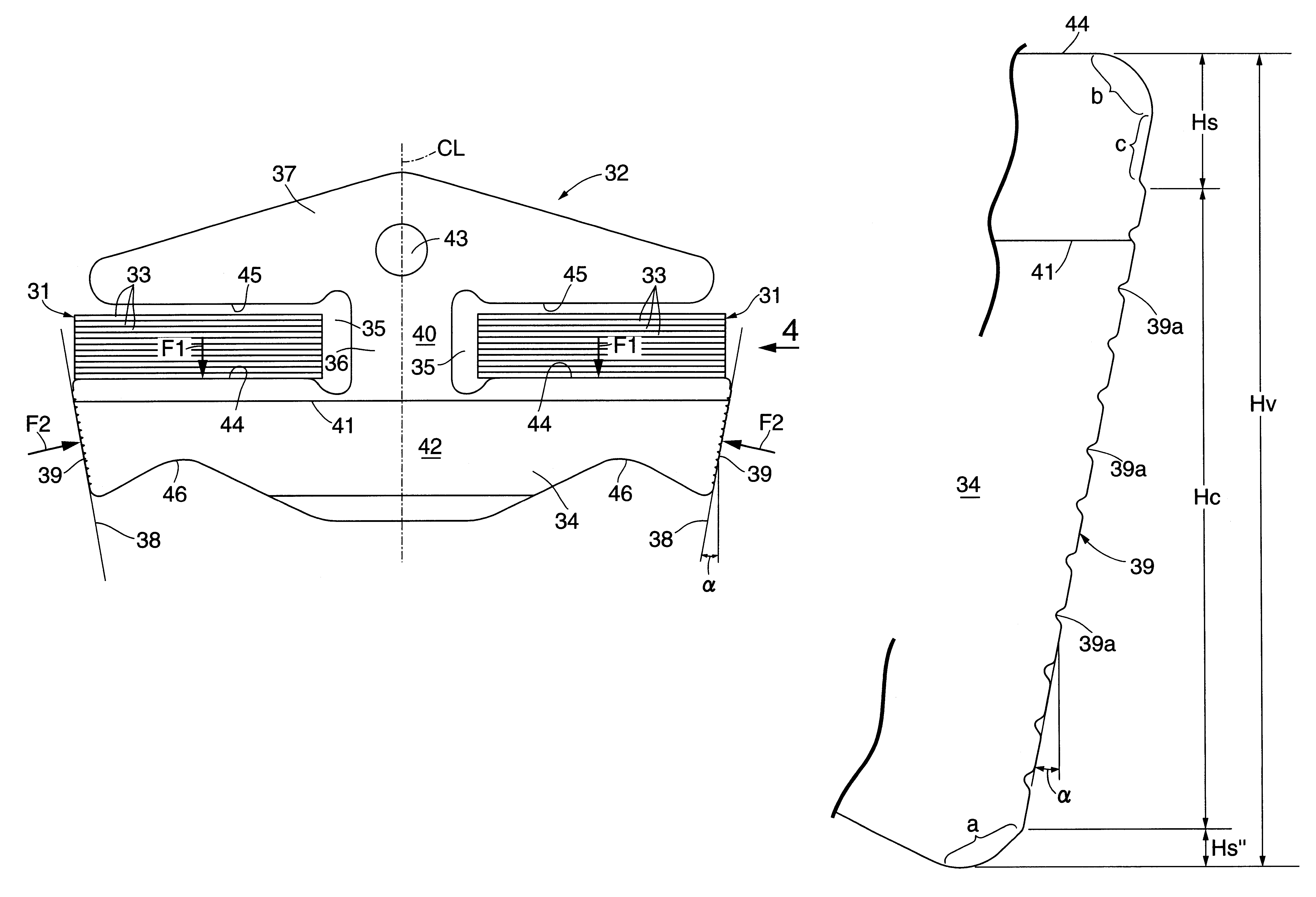
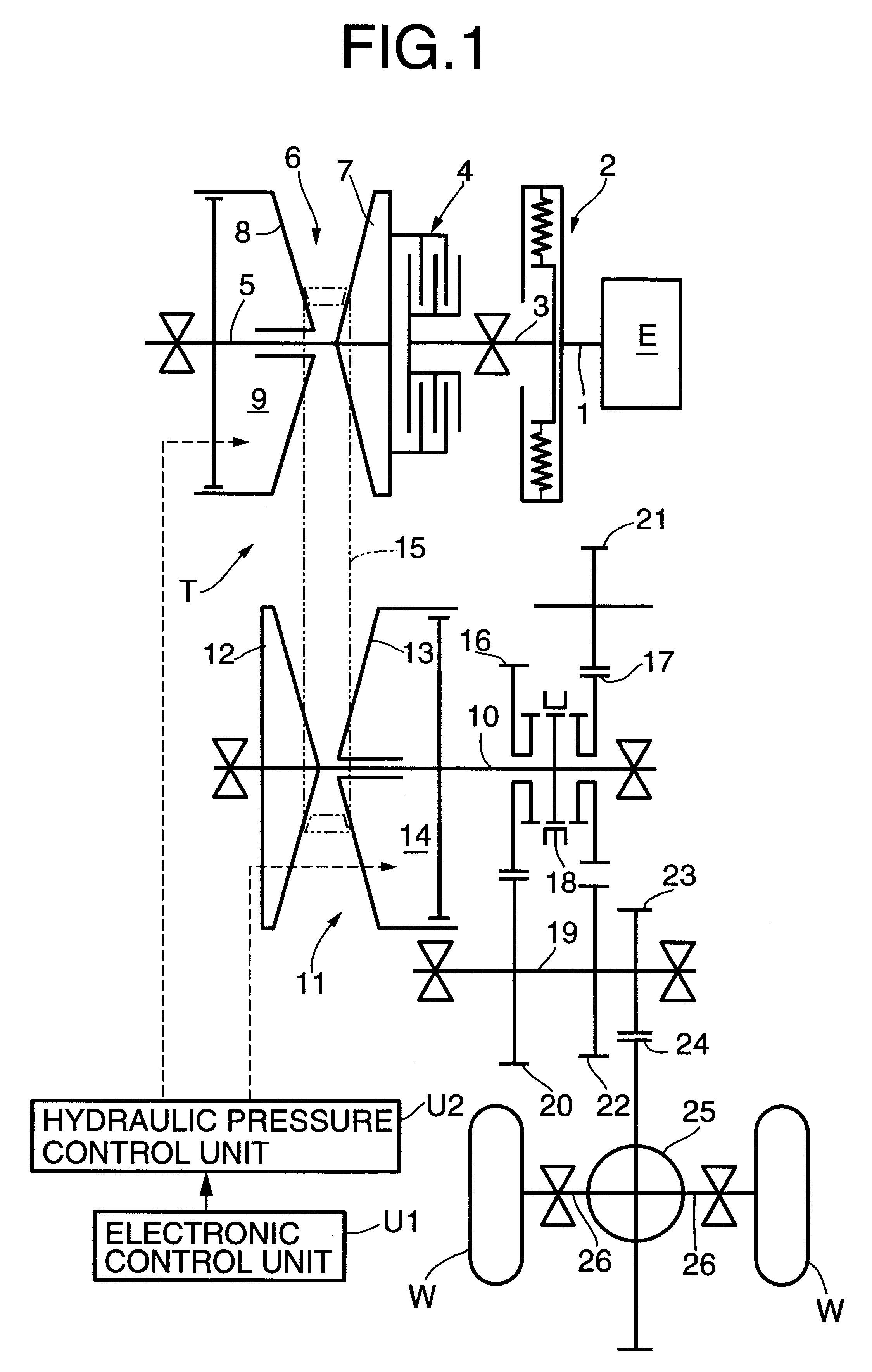
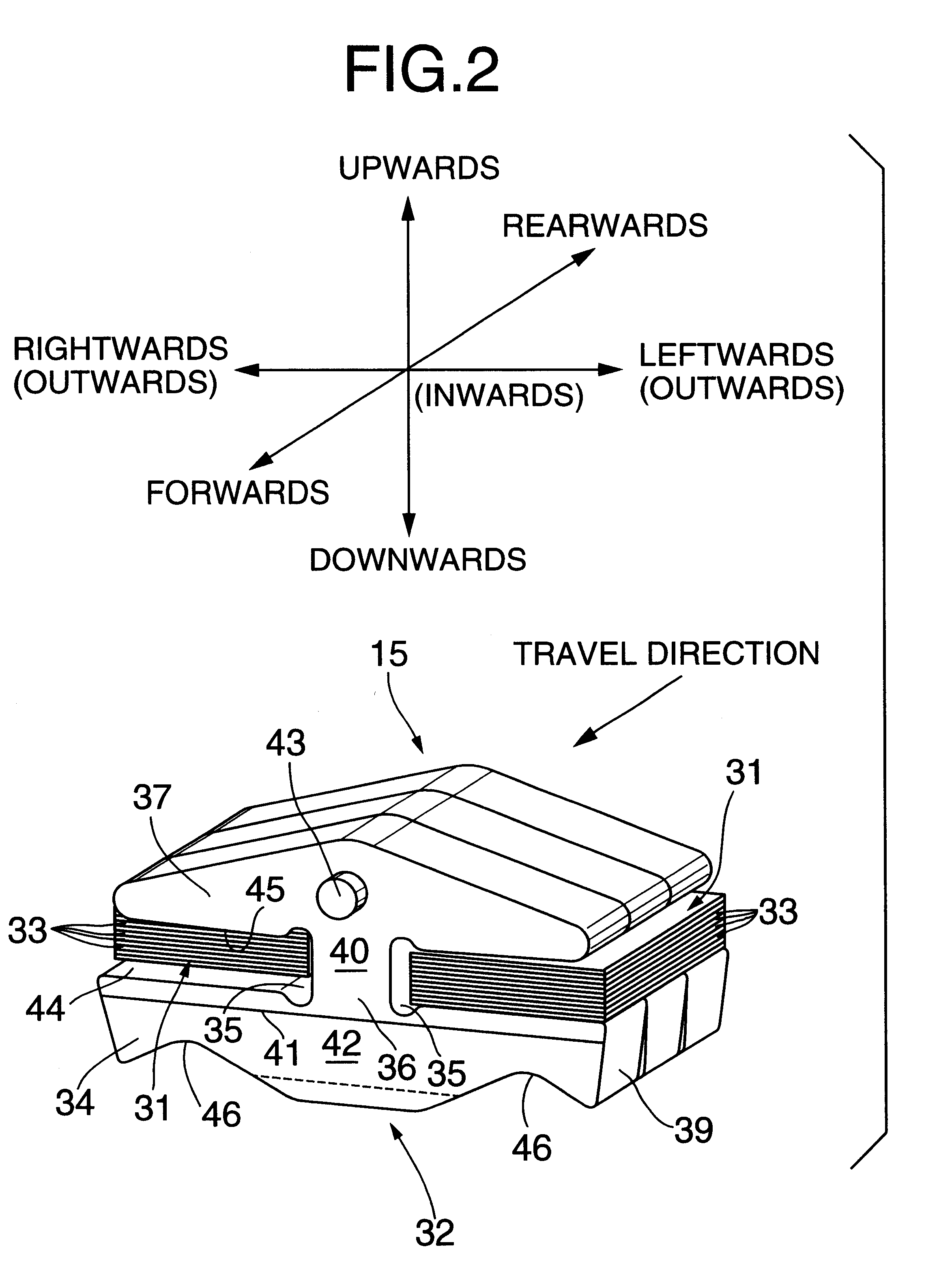
FIGS. 1 to 9 show a first embodiment of the present invention. FIG. 1 is a skeletal diagram of a power-transmitting system in a vehicle provided with a continuously variable transmission; FIG. 2 is a partially perspective view of a metal belt; FIG. 3 is a front view of a metal element; FIG. 4 is a view taken in the direction of an arrow 4 in FIG. 3; FIG. 5 is an enlarged view of an essential portion shown in FIG. 3; FIGS. 6A and 6B are diagrams showing deformation of the metal element due to a load; FIGS. 7A and 7B are diagrams showing the distribution of a bending moment applied to a saddle face; FIG. 8 is a graph showing ranges of the height Hv of a V-face and the height Hs of an upper non-contact portion in which the parallelism of the V-face is lower than .+-.1 .mu.m; and FIG. 9 is a graph showing the relationship between the par...


PUM


Abstract

A V-face of a metal element is prevented from being inclined due to a load from a pulley by increasing the height Hs of an upper non-contact portion of the V-face of the metal element. For example, when the height of the V-face is represented by Hv (mm), and the height of the upper non-contact portion of the V-face is represented by Hs (mm), the height Hv of the V-face and the height Hs of the upper non-contact portion are set so that a relationshipis established.

Description

The present invention relates to a belt for a continuously variable transmission, in which a pair of left and right ring slots defined in each of a plurality of metal elements are supported on a pair of left and right metal ring assemblies with each formed of a plurality of endless metal rings laminated one on another, respectively, and which is wound around a drive pulley and a driven pulley to transmit a driving force.A belt for the continuously variable transmission suffers from the following problem: When left and right V-faces of the metal element receive an axial load from the V-grooves of the pulley, if the V-faces of the metal element are moved in an inclined manner rather than in parallel by the load, one end of the V-face is brought vertically into strong contact with the V-groove and as a result, the other end is lifted from the V-groove of the pulley, whereby an uneven wearing occurs in the metal element and the pulley.Therefore, the inventor has proposed a belt for a co...

Claims


Application Information

Patent Timeline
Patent Type & Authority Patents(United States)
IPC IPC(8): F16G5/00F16G5/16
CPCF16G5/16F16G5/163
Inventor KANOKOGI, KENYOSHIDA, HIDEAKI
Owner HONDA MOTOR CO LTD
Why Eureka
Try Eureka