Trolley and traveling block system

a technology of traveling block and trolley, which is applied in the direction of drilling machine and method, fluid removal, construction, etc., can solve the problems of time and labor costs associated with the handling of the injector upon switching tasks, the inability to locate or identify, and the removal of the injector

Inactive Publication Date: 2003-08-26
NABORS CANADA
View PDF6 Cites 69 Cited by
  • Summary
  • Abstract
  • Description
  • Claims
  • Application Information

AI Technical Summary

Benefits of technology

According to the present invention, there is provided in one aspect a trolley hoisting system for use in a rig comprising a winch line extending from an upper end of a rig derrick having a traveling block at a lower end thereof, and an injector housing having at least one cavity for allowing the winch line passage therethrough and being adapted to engage the traveling block so that the winch line may be used to raise and lower the injector and injector housing along the derrick, and a lock arrangement for fixing the injector housing to the derrick at an upper end thereof to allow the traveling block to extend below the injector housing for performing other desired tasks on the rig.

Problems solved by technology

We have not been able to locate or identify any conventional derricks, whether they use a single winch or a similar multiple (i.e. two or more) winch system, which would allow one winch arrangement to handle multiple tasks without having to decouple the winch from the injector and remove the injector from the mast, or where the injector superstructure is not thereafter interfering with movement of the mainblock winch lines and the joined pipe or other downhole equipment being handled.
In particular, there are time and labour costs associated with handling of the injector upon switching tasks.
Removal of the injector from the plane of the mast to enable access and use of a winch or hoisting system is labour and time consuming.
The costs and difficulties are further augmented if the winch line moving the injector must also be disconnected or moved from the injector mechanism before using it for another desired task.
Further, in a multiple winch system where the primary winch line is not disconnected from the injector, the secondary winch is typically slower and has less capacity than the primary line, leading to further inefficiencies.

Method used


Image

  • Trolley and traveling block system
  • Trolley and traveling block system
  • Trolley and traveling block system

Examples


Embodiment Construction

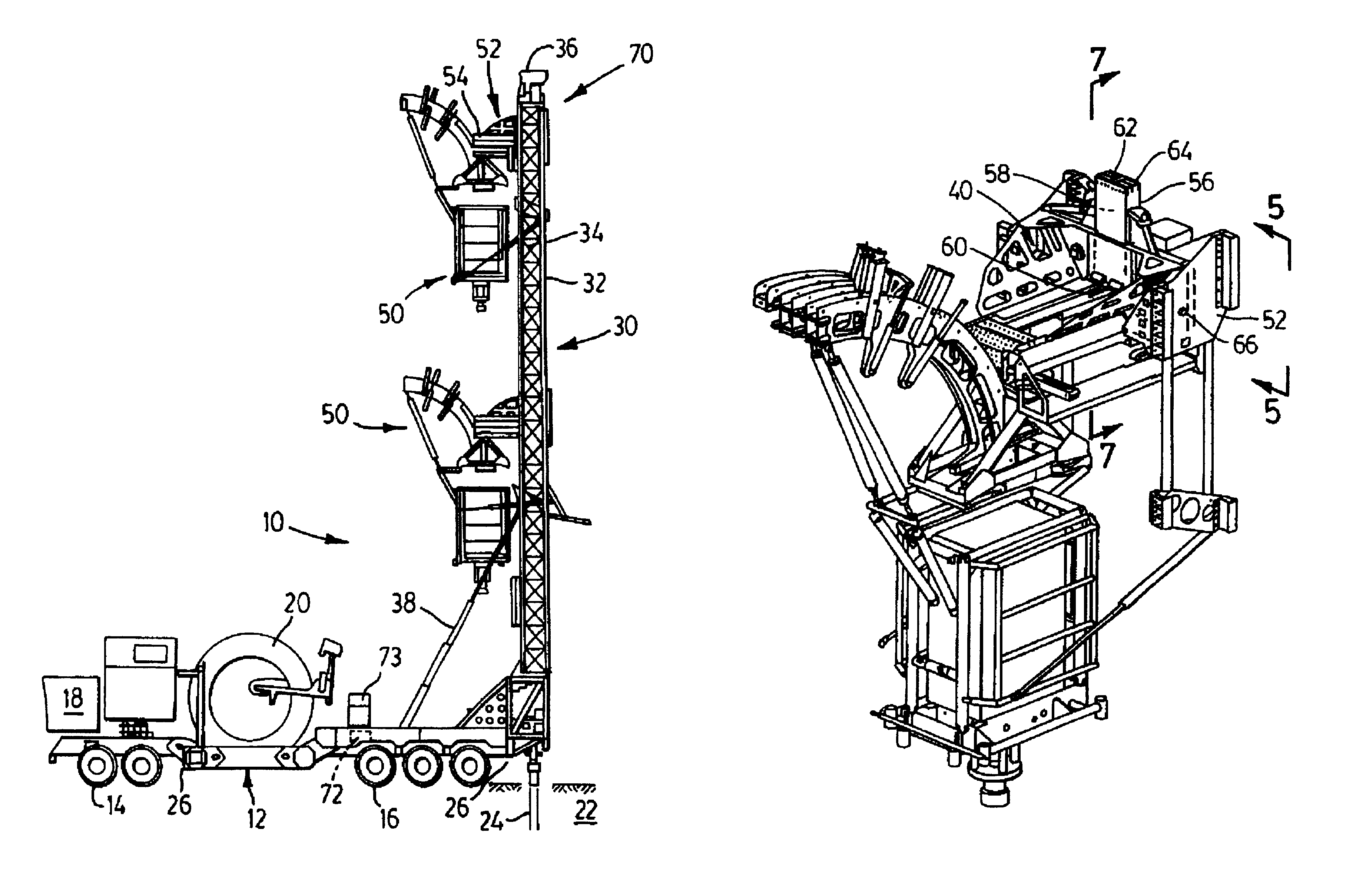
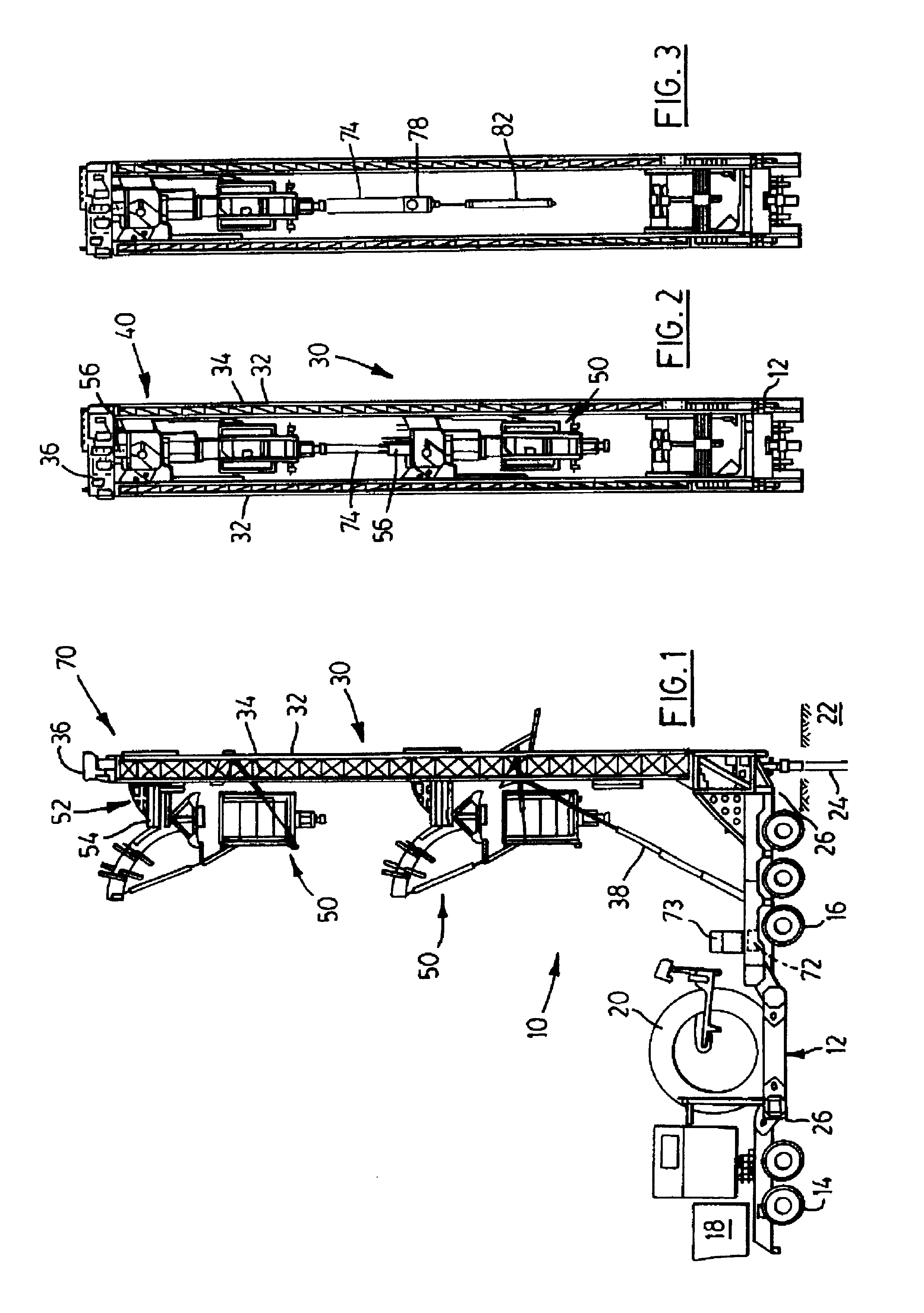
FIG. 1 shows a mobile rig 10 for transporting drilling and servicing equipment to an oil or gas well site. The equipment, such as a cartridge assembly 20 capable of holding various sizes of continuous or coiled tubing ("CT") reels, is located aboard a self-propelled carrier 12 having a tandem axle front end 14 and a triple axle rear end 16. A cab 18 houses an engine for driving the front and / or rear axles, and incorporates conventional controls for steering the carrier over a ground surface 22 and for locating the carrier's rear end over a well. The term "well" is understood herein to mean either an oil or gas well to be drilled, or an existing well or wellhead 24 which is to be tested or serviced. The carrier 12 incorporates a number of hydraulically operated stabilizers 26 for lifting the carrier off the ground and enhancing lateral stability during well operations. The front and rear axle designs may vary depending on the anticipated weight of equipment to be carried and the type...


PUM


Abstract

A trolley hoisting system for use in a rig has a derrick mounted to the rig, a winch line extending from an upper end of the derrick, and a traveling block located at one end of the winch line. An injector trolley has at least one cavity for allowing the winch line passage therethrough and is adapted to engage the traveling block so that the winch line may be used to raise and lower the injector trolley along the derrick. A lock arrangement for fixing the injector trolley to the derrick at an upper end thereof allows the traveling block to extend below the injector trolley for performing other desired tasks on the rig.

Description

The present invention relates to drilling and servicing equipment for oil and gas wells generally, and in particular relates to a trolley hoisting system for use in rigs which transport and / or operate equipment for continuous coiled tubing drilling, for conventional joined pipe handling and drilling, and / or for wireline applications.Our U.S. Pat. No. 6,003,598 and corresponding Canadian Patent 2,235,555 for a "Mobile Multi-Function Rig" disclose a dual winch arrangement atop a pivotable derrick, or masts, for performing various functions relating to drilling and servicing either oil or gas wells. One of the winch systems, namely the derrick or mainblock winch, is used to raise and lower certain equipment along the mast, such as an injector and lubricator for continuous or coiled tubing (referred to herein as "CT"). A secondary, or fastline, winch is used to manipulate other equipment, such as a blow-out-preventer ("BOP"). For operations requiring use of a traveling block and elevato...

Claims


Application Information

Patent Timeline
Patent Type & Authority Patents(United States)
IPC IPC(8): E21B19/22E21B19/02E21B19/00E21B15/00
CPCE21B15/00E21B19/02E21B19/22
Inventor ANDREYCHUK, MARK T.RIKE, JR., EMANUEL A.
Owner NABORS CANADA
Why Eureka
Try Eureka