Railroad grade crossing assembly

a grade crossing and assembly technology, applied in the direction of traffic gates, ways, constructions, etc., can solve the problems of potential disaster, railroads are currently under pressure to put in additional gates, etc., and achieve the effect of being ready to attach

Inactive Publication Date: 2003-09-16
SAFE CROSSINGS
View PDF8 Cites 37 Cited by
  • Summary
  • Abstract
  • Description
  • Claims
  • Application Information

AI Technical Summary

Benefits of technology

It is another object of this invention to provide a railroad grade crossing assembly which not only allows a gate crossing to be completely closed but also is adaptable to an existing stanchion and light assembly.
It is a further object of the present invention to provide a railroad grade crossing assembly which completely closes the gate crossing and complies with the time requirements for closing a railroad crossing which are mandated by federal, state and municipal governments.
It is yet another object of the present invention to provide a relatively inexpensive railroad grade crossing assembly capable of completely closing the gate crossing.
It is still another object of the invention to provide a railroad grade crossing assembly which can be readily attached to the arm of an existing railroad grade crossing system.

Problems solved by technology

Therefore, the present railroad gates allow for a vehicle operator to make an S turn across the track thereby creating the potential for disaster.
As a result, the railroads are currently under pressure to put in additional gates to completely close vehicle access to the tracks.
A drawback in designing a railroad gate which completely closes the gate crossing is that is must comply with time requirement for closing a railroad crossing which are determined by federal, state and municipal governments.

Method used


Image

  • Railroad grade crossing assembly
  • Railroad grade crossing assembly
  • Railroad grade crossing assembly

Examples


first embodiment

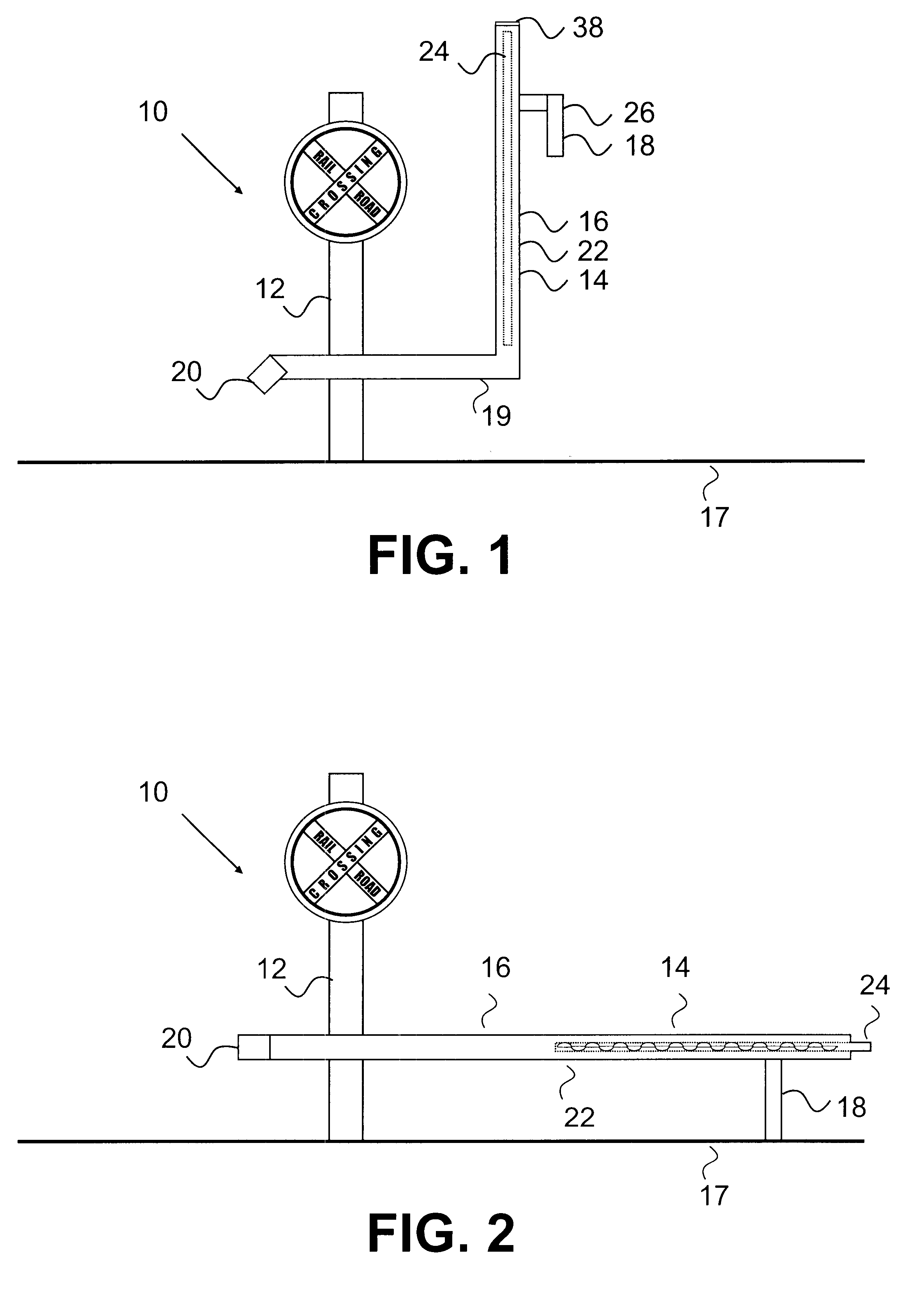
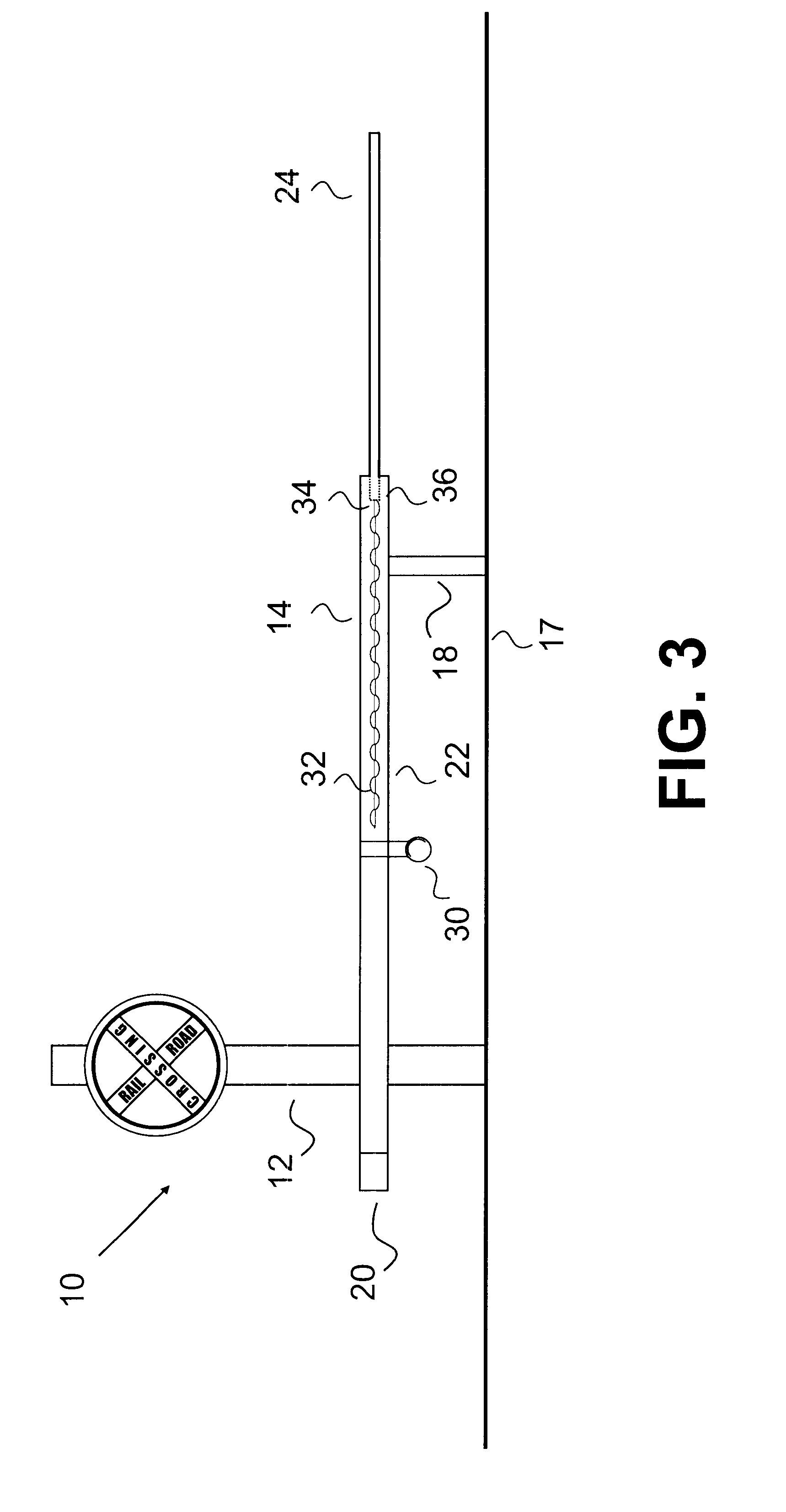
Referring now to FIGS. 1 through 3 of the drawings, a railroad grade crossing assembly in accordance with the teachings of the present invention is illustrated. This railroad grade crossing assembly 10 of the present invention can be adapted to an existing stanchion and light assembly 12 which included a gate assembly (not shown) which only partially closed the railroad crossing.

Here, the railroad grade crossing assembly 10 of the present invention is formed of an improved gate assembly 14 which is connectable to the existing stanchion and light assembly 12. As is shown in FIGS. 1 through 3, the gate assembly 14 includes a two piece telescopic arm assembly 16 and a gravity actuated support leg 18. This arm assembly is movable between a generally upright position (see FIG. 1) and a generally horizontal position (see FIGS. 2 and 3). In the generally upright position of the arm assembly 14 of FIG. 1, the base of the arm assembly 19 is held in a generally horizontal orientation by a cou...

second embodiment

a railroad grade crossing assembly according to the present invention is illustrated in FIGS. 4-7.

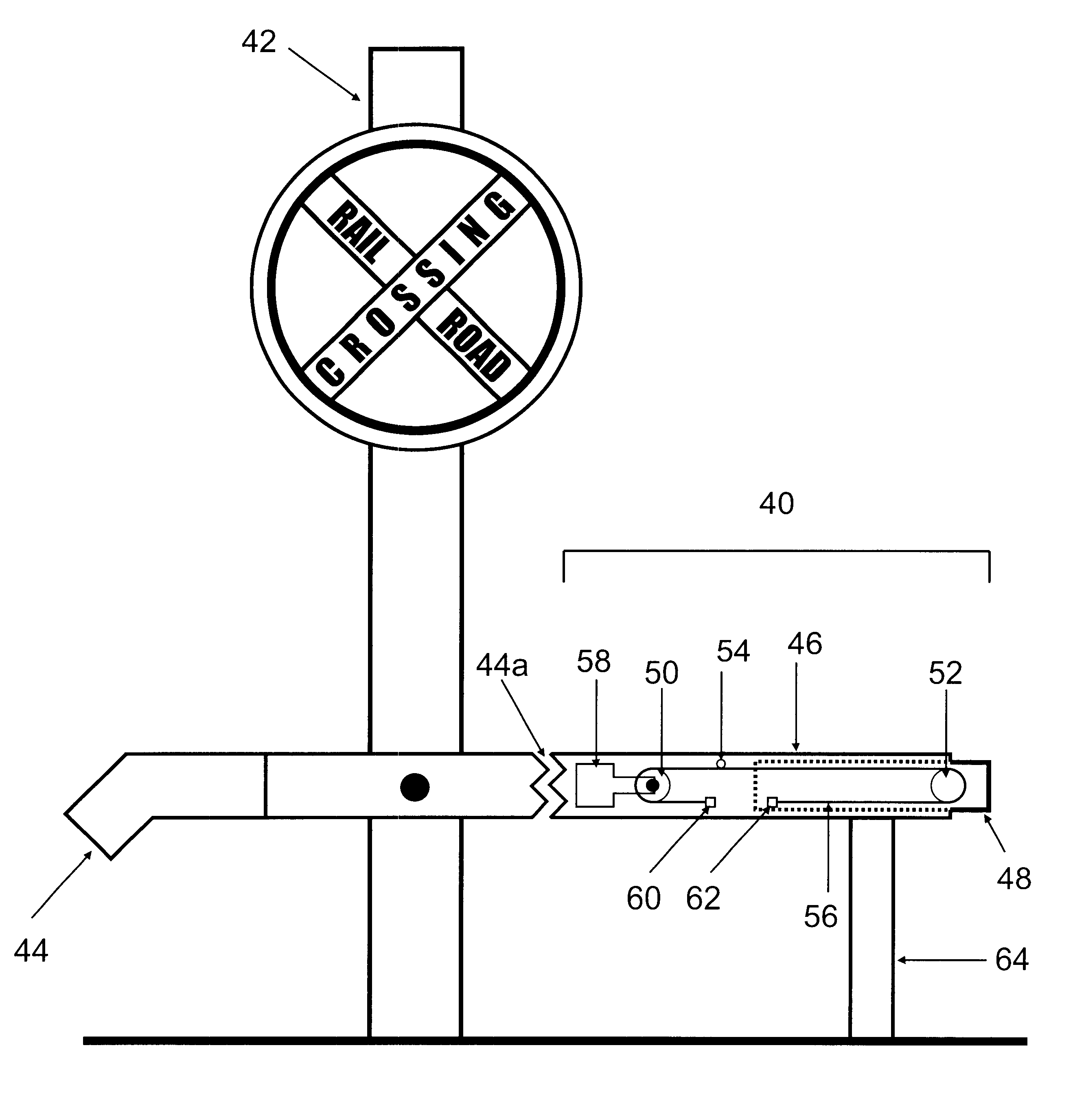
FIG. 4 is a plan view showing a railroad grade crossing assembly 40 according to the second embodiment, and showing how the railroad grade crossing assembly according to the second embodiment can be attached to a preexisting stanchion 42 and arm assembly 44. As can be seen from the figure, the crossing assembly includes an outer gate 46 and an inner (or "telescoping") gate 48. The assembly of the invention is attached to a preexisting stanchion 42 and arm 44 by cutting arm 44 as indicated at position 44a and then splicing outer gate 46 to the arm.

More specifically, the crossing assembly of the invention can be employed at existing railroad crossings by laying assembly 40 across the roadway where it is to be used such that the assembly in its extended state would completely close the roadway at the location of the existing stanchion. Once the assembly is laid out in this fashion, one can...

third embodiment

Referring now to FIG. 7 of the drawings, a railroad grade crossing assembly in accordance with the teachings of the present invention is illustrated. This railroad gate crossing assembly 110 of the present invention is self contained and can be adapted to an existing stanchion and light assembly 112 which may or may not included a gate assembly (not shown) which only partially closed the railroad crossing. The assembly provides its own power supply.

Here, the railroad grade crossing assembly 110 of the present invention is formed of an improved gate assembly 140 which is connectable to the existing stanchion 112. As can be seen from the figure, the crossing assembly includes an outer gate 146 and an inner (or "telescoping") gate 148. The assembly of the invention is attached to a preexisting stanchion 112.

More specifically, the crossing assembly of the invention can be employed at existing railroad crossings by laying assembly 140 across the roadway where it is to be used such that t...


PUM


Abstract

A railroad grade crossing assembly for blocking vehicle access across a railroad crossing including a gate assembly connectable to a stanchion and light assembly. This gate assembly is movable between a generally upright position to permit vehicle access across a railroad crossing and a generally horizontal position for blocking vehicle access across the railroad crossing. The gate assembly further includes a telescopic arm assembly for completely closing vehicle access to the railroad crossing. In another embodiment of the invention, the railroad grade crossing assembly includes a gate movable between a generally horizontal retracted position to permit vehicle access across a railroad crossing and a generally extended horizontal position for blocking vehicle access across a railroad crossing, the gate includes a telescopic arm for completely closing the railroad crossing, a first and second stanchions. The railroad grade crossing assembly also includes a battery to power the gate and a solar panel to recharge the battery. A low battery indicator may also be includes to indicate that said battery has a low voltage. A listening device is provided to detect the sound of an oncoming train and activate the gate, and a sensor is provided to sense when a train has passed and thereby cause the gate to retract.

Description

The present invention relates to an improved railroad grade crossing assembly, and more particularly, to a railroad grade crossing assembly which is extendable to fully close the road or street leading to the track.Railroad grade crossing assemblies that are currently in use only close the road in the direction of traffic to within one foot of the center line. Therefore, the present railroad gates allow for a vehicle operator to make an S turn across the track thereby creating the potential for disaster. As a result, the railroads are currently under pressure to put in additional gates to completely close vehicle access to the tracks. It has therefore been found desirable to provide a railroad gate which allows a gate crossing to be completely closed prior to the arrival of a train.A drawback in designing a railroad gate which completely closes the gate crossing is that is must comply with time requirement for closing a railroad crossing which are determined by federal, state and mu...

Claims


Application Information

Patent Timeline
Patent Type & Authority Patents(United States)
IPC IPC(8): E01F13/00E01F13/06B61L29/22
CPCB61L29/22E01F13/06B61L29/04
Inventor BURKE, THOMAS J.
Owner SAFE CROSSINGS
Why Eureka
Try Eureka