Vehicle lamp

a technology for vehicles and lamps, applied in the field of vehicles, can solve the problems of insufficient arrangement above, changeless appearance of conventional vehicle lamps,

Inactive Publication Date: 2003-09-16
KOITO MFG CO LTD
View PDF15 Cites 50 Cited by
  • Summary
  • Abstract
  • Description
  • Claims
  • Application Information

AI Technical Summary

Benefits of technology

Although the light source positioned in the rear of the condenser lens appears magnified, the provision of the diffusion lens therebetween allows the light source to be hardly visible because of the diffusive action of light passing through the diffusion lens. In so doing, moreover, it is possible to make the luminosity of the whole light source in the on state look substantially uniform over a wide luminescent area.
With the arrangement above, the provision of the non-half-mirror portion or the opening portion in the central position of the translucent panel, as well as in a plurality of peripheral positions surrounding the central position) provides an enhanced lamp design for the vehicle lamp in the on state and off state both.

Problems solved by technology

However, conventional vehicle lamps appear changeless in the case where the vehicle lamps are on and in the case where the vehicle lamps are off.
With respect to the way the vehicle lamp looks while the vehicle lamp is in the on state, the arrangement above is also insufficient because the hidden light source looks luminous only while vehicle lamp is in the off state.

Method used


Image

  • Vehicle lamp
  • Vehicle lamp
  • Vehicle lamp

Examples


Embodiment Construction

Reference will now be made to the drawings that illustrate an embodiment for carrying out the present invention.

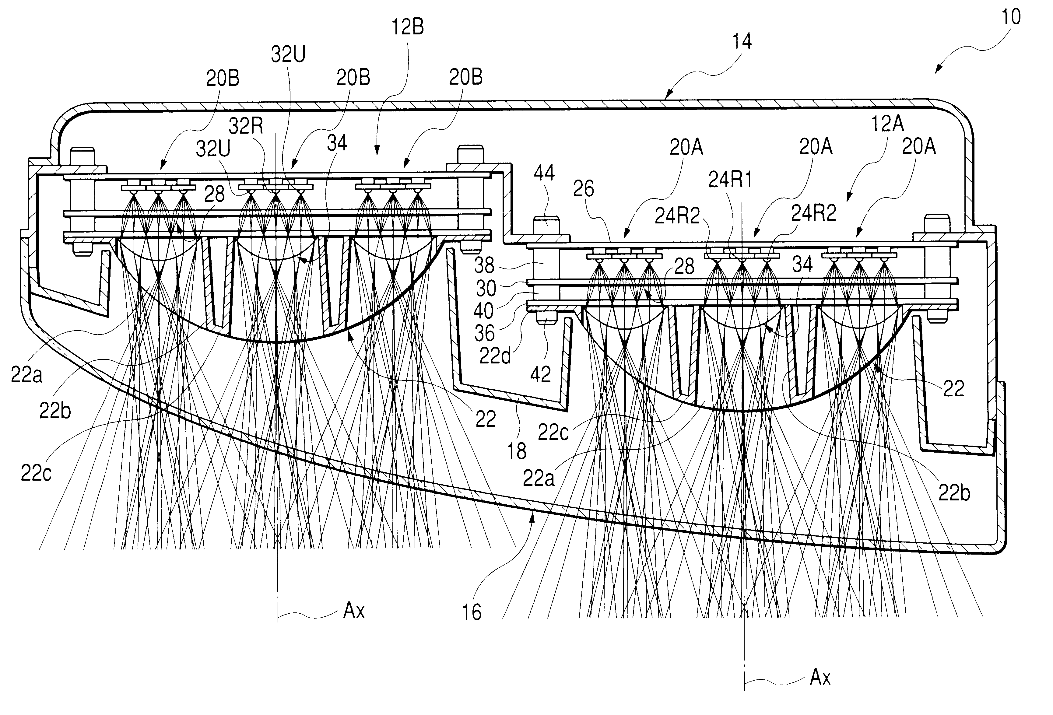
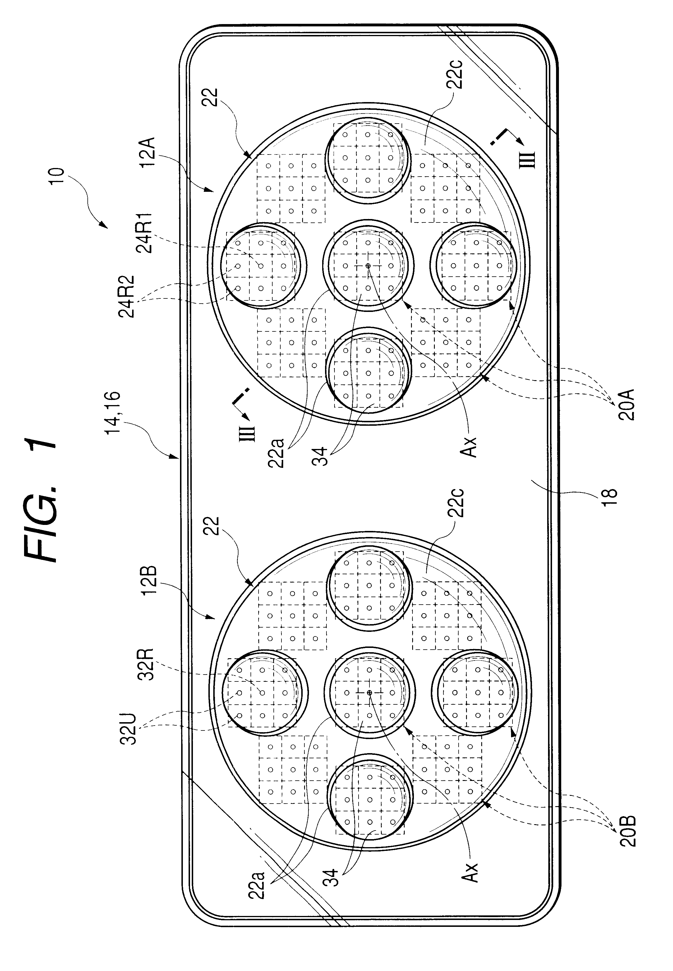
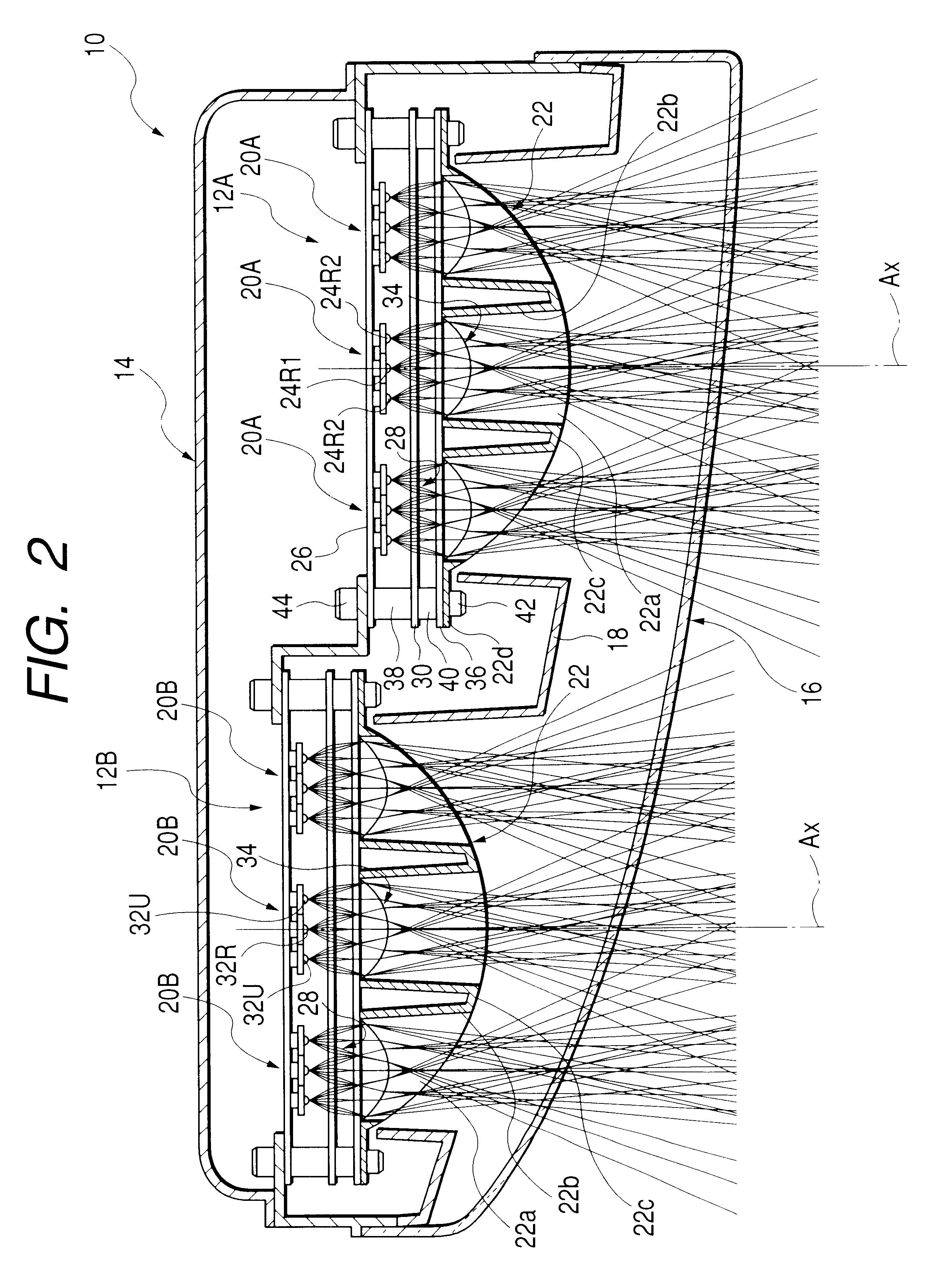
FIG. 1 is an elevation view of a vehicle lamp 10 embodying the present invention. FIG. 2 is a horizontal sectional view thereof, and FIG. 3 is a detailed sectional view taken on line III--III of FIG. 1.

As shown in these drawings, the vehicle lamp 10 according to the present invention is a rear combination lamp installed in the left-side rear end portion of a vehicle. The vehicle lamp 10 comprises a pair of lamp units 12A and 12B contained in a lamp chamber formed with a lamp body 14 having a contour that is long sideways and with a plain translucent cover 16. In addition, a shielding panel 18 surrounds these lamp units 12A and 12B.

The vehicle lamp 10 functionally serves as a tail lamp, a stop lamp and a turn-signal lamp. Specifically, the lamp unit 12A positioned on the inner side of the vehicle in the width direction thereof can be turned on in a tail lamp lighting mode a...


PUM


Abstract

A lamp unit having a dome-shaped translucent panel disposed in front of several light sources is provided. Opening portions corresponding to certain light sources are formed crosswise in the translucent panel. A condenser lens is provided in the rear of each opening portion in the translucent panel. The dome-shaped portion of the translucent panel is formed as a half-mirror portion, whereby five small cross-shaped translucent domes are visible when the vehicle lamp is in an off state. The light sources positioned to the rear of the opening portions and the light sources positioned to the rear of the half-mirror portions provide an unexpected luminous intensity distribution.

Description

BACKGROUND OF THE PRESENT INVENTION1. Technical Field of the InventionThe present invention relates to a vehicle lamp and more particularly to a structure for improving the appearance of the vehicle lamp.2. Prior ArtA typical vehicle lamp comprises a light source, a lamp body for supporting the light source and a translucent cover mounted on the lamp body. However, conventional vehicle lamps appear changeless in the case where the vehicle lamps are on and in the case where the vehicle lamps are off.On the other hand, the adoption of a vehicle lamp with its translucent cover (the light cover) subjected to half-mirror processing as disclosed in JP-2-22505U results in making the interior of the vehicle lamp in the on state visible. The half-mirror processing also makes the interior thereof (in the vehicle lamp off state) invisible due to the external light reflective action of the translucent cover, whereby the vehicle lamp in the on state can look quite different from what is in the o...

Claims


Application Information

Patent Timeline
Patent Type & Authority Patents(United States)
IPC IPC(8): F21V5/00F21S8/10F21V13/00F21V13/04F21W101/14F21W107/10F21Y101/02
CPCF21S48/215F21S48/2212F21S48/24F21S48/25F21Y2101/02F21Y2115/10F21S43/14F21S43/26F21S43/40F21S43/50
Inventor NATSUME, KAZUNORI
Owner KOITO MFG CO LTD
Why Eureka
Try Eureka