Toner container and image forming apparatus
a technology of toner container and image forming apparatus, which is applied in the direction of electrographic process apparatus, instruments, optics, etc., can solve the problems of unsatisfactory impression given to users, and achieve the effect of preventing the abnormal connection of the toner outlet with the toner supply opening
- Summary
- Abstract
- Description
- Claims
- Application Information
AI Technical Summary
Benefits of technology
Problems solved by technology
Method used
Image
Examples
first embodiment
[0066][First Embodiment]
[0067]Referring to FIGS. 1 through 35, a first embodiment of the present invention is described in detail.
[0068]First, a structure and operations of an image forming apparatus are described.
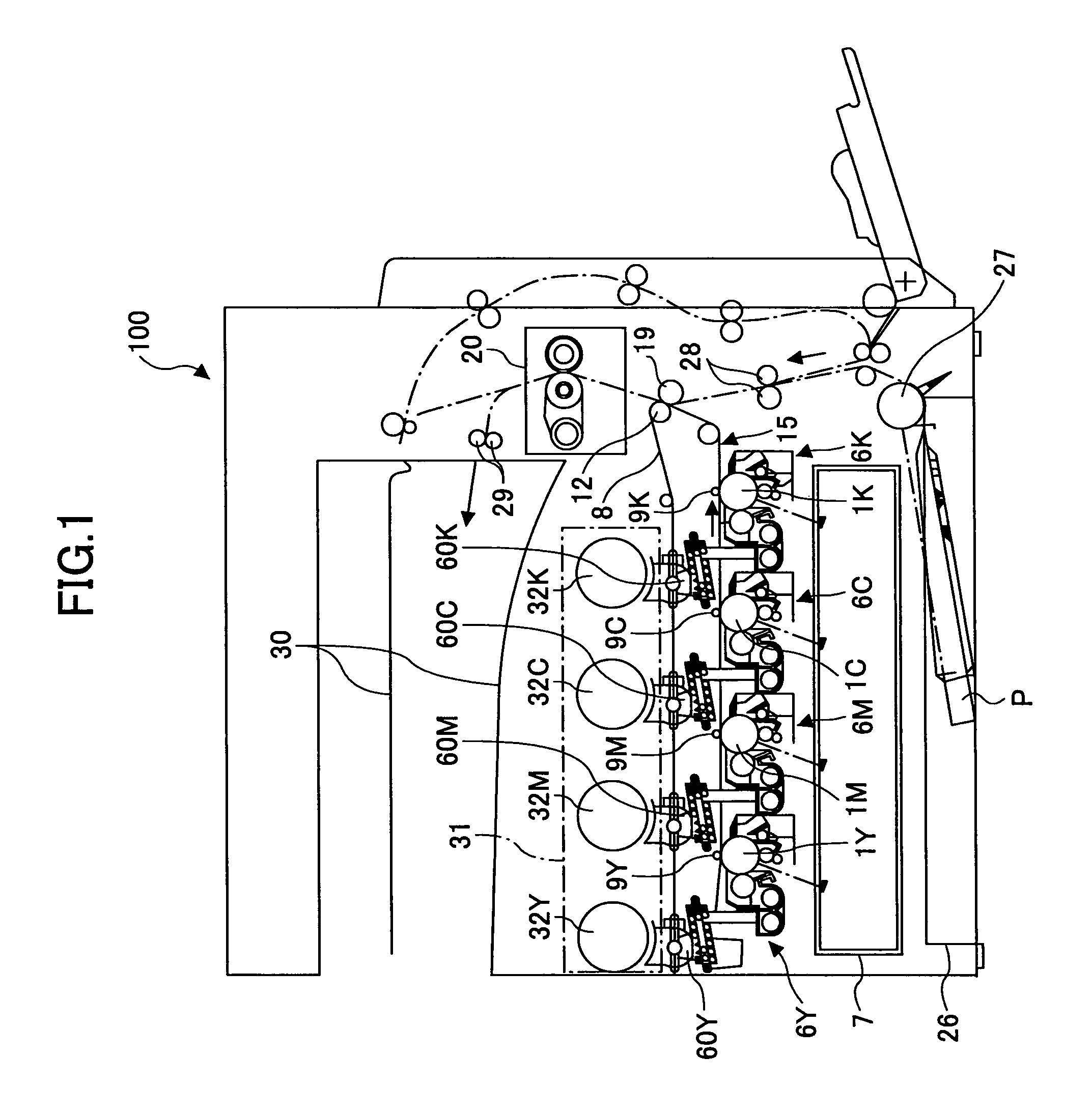
[0069]FIG. 1 is a schematic diagram showing a part of a structure of an image forming apparatus main body 100 of an image forming apparatus according to the first embodiment of the present invention.
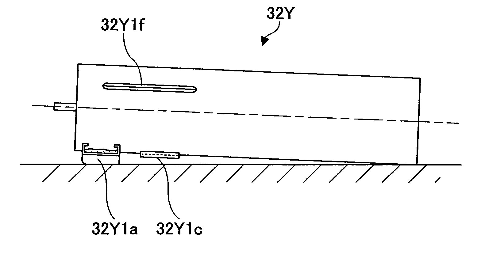
[0070]As shown in FIG. 1, in a toner container storing section 31 at an upper part of the image forming apparatus main body 100, four toner containers 32Y, 32M, 32C, and 32K corresponding to four colors yellow, magenta, cyan, and black are detachably attached to the toner container storing section 31.
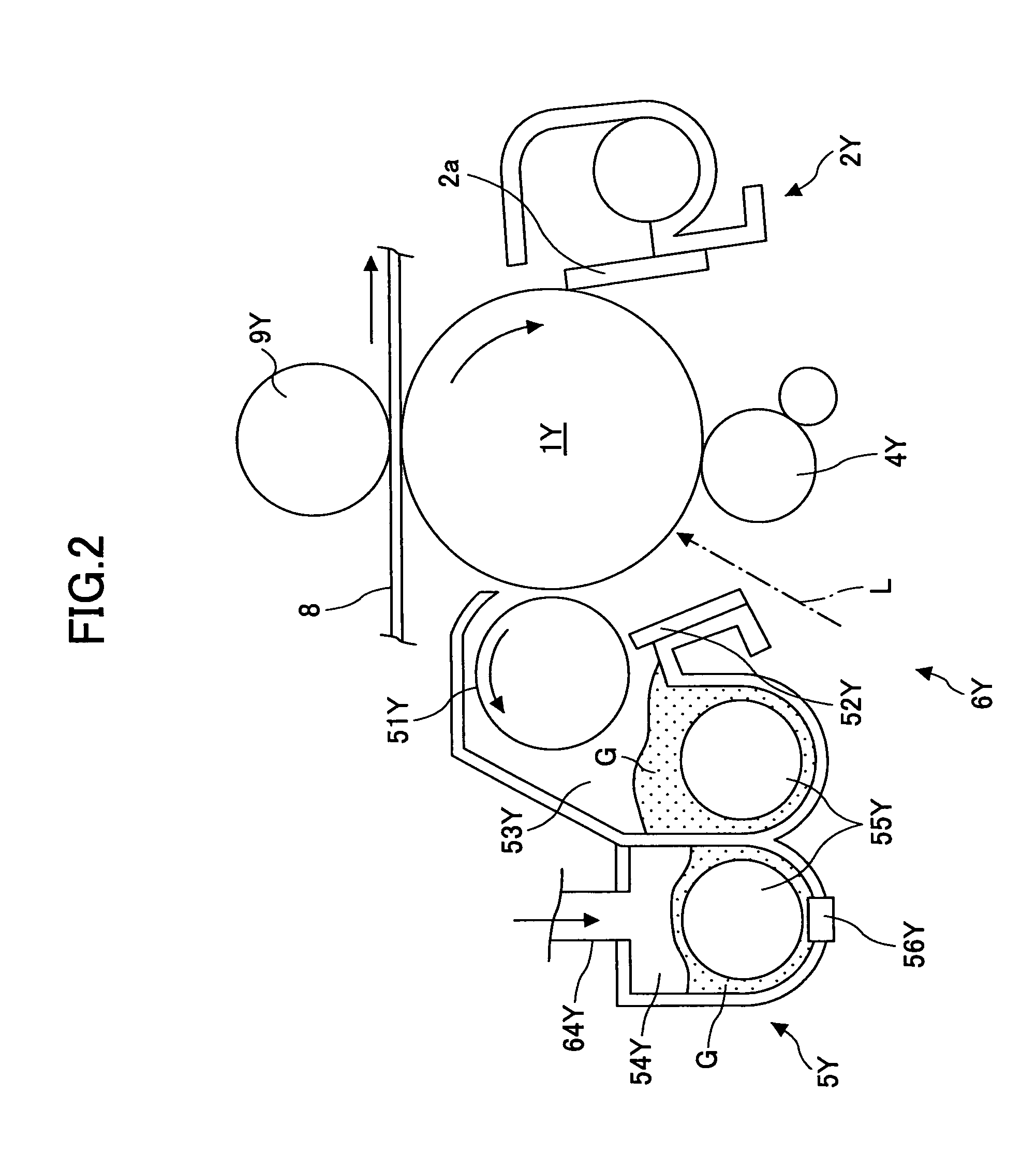
[0071]An intermediate transfer unit 15 is provided under the toner container storing section 31. The intermediate transfer unit 15 includes an intermediate transfer belt 8. Image forming sections 6Y, 6M, 6C, and 6K corresponding to the four colors yellow, magenta, cyan, and black a...
second embodiment
[0233][Second Embodiment]
[0234]Next, referring to FIGS. 36 and 37, a second embodiment of the present invention is described. FIG. 36 is a perspective view of a toner container according to the second embodiment of the present invention, and FIG. 37 is a cut-away side view of a head part of the toner container shown in FIG. 36. In the second embodiment of the present invention, as the reference number of the toner container, the same reference number 32Y as that in the first embodiment of the present invention is used.
[0235]When the second embodiment of the present invention is compared with the first embodiment of the present invention, in the second embodiment of the present invention, the head part of the toner container 32Y has a circular cone shape, and the scrapers 32Y30 are not positioned at the opening of the container main body 32Y2.
[0236]As shown in FIGS. 36 and 37, similar to the first embodiment of the present invention, in the second embodiment of the present invention,...
third embodiment
[0245][Third Embodiment]
[0246]Referring to FIGS. 38 and 39, a third embodiment of the present invention is described. FIG. 38 is a cut-away side view of a toner container according to the third embodiment of the present invention and FIG. 39 is a cut-away side view of another toner container according to the third embodiment of the present invention. In the third embodiment of the present invention, as the reference number of the toner container, the same reference number 32Y as that in the first embodiment of the present invention is used.
[0247]When the third embodiment of the present invention is compared with the first embodiment of the present invention, in the third embodiment of the present invention, a carrying member 320 is formed inside the toner container 32Y.
[0248]As shown in FIG. 38, the toner container 32Y includes a container main body which is secured to the image forming apparatus main body 100 when the container main body is attached to the image forming apparatus m...
PUM
 Abstract
Description
Claims
Application Information
 - R&D
- Intellectual Property
- Life Sciences
- Materials
- Tech Scout
- Unparalleled Data Quality
- Higher Quality Content
- 60% Fewer Hallucinations
Browse by: Latest US Patents, China's latest patents, Technical Efficacy Thesaurus, Application Domain, Technology Topic, Popular Technical Reports.
© 2025 PatSnap. All rights reserved.Legal|Privacy policy|Modern Slavery Act Transparency Statement|Sitemap|About US| Contact US: help@patsnap.com


