
Method for manufacturing semiconductor devices and plug

a manufacturing method and technology for semiconductor devices, applied in the direction of semiconductor devices, basic electric elements, electrical equipment, etc., can solve the problems of increasing the difficulty of manufacturing process, increasing the demand for size precision, and exposure of other component devices, so as to prevent current leakage or abnormal electrical performance. , the effect of increasing the number o

Active Publication Date: 2008-05-06
POWERCHIP SEMICON MFG CORP
View PDF8 Cites 0 Cited by
  • Summary
  • Abstract
  • Description
  • Claims
  • Application Information

AI Technical Summary

Benefits of technology

The present invention provides a fabrication method for a semiconductor device that prevents abnormal connections between components and prevents current leakage or abnormal electrical performance. This is achieved by forming a depression between the conducting structure and the substrate, which prevents the conducting structure from being connected to the upper conducting structure. The method also includes a wet etching process using a mixture of ammonia solution and hydrogen peroxide to remove a portion of the select gate and form a via plug. The method improves the reliability and performance of the semiconductor device.

Problems solved by technology

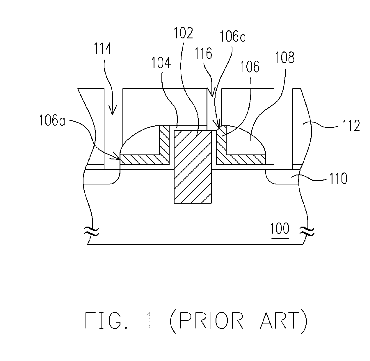
However, due to the miniaturizing of component devices, the difficulties in the manufacturing process greatly increase, and the demand for size precision also increases.
Furthermore, the misalignment during the photolithography process often leads to an exposure of other component devices neighbouring to the source / drain region, the gate or the interconnect, designated to be exposed.
Therefore, while forming contact plugs in the contact window 114 and the 116, the contact plugs are connected to the exposed select gate 106 through abnormal electrical connection, leading to current leakage for the device, and abnormal electrical performance.

Method used


Image

  • Method for manufacturing semiconductor devices and plug
  • Method for manufacturing semiconductor devices and plug
  • Method for manufacturing semiconductor devices and plug

Examples


first embodiment

The First Embodiment

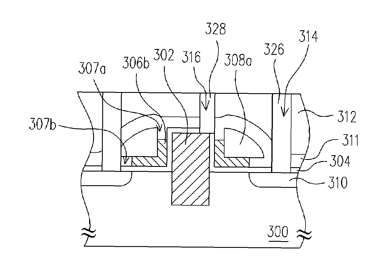
[0020]According to the present invention, the foregoing general description and the following detailed description of an embodiment with reference to the accompanying drawings are exemplary and explanatory for a plug fabrication of a trench type flash memory process. This invention, however, may be embodied in many different forms and should not be construed as limited to the embodiments set forth herein. The present invention is applicable to any process that is related to the formation of a plug in a dielectric layer, wherein the plug is electrically connected to an adjacent device underneath.

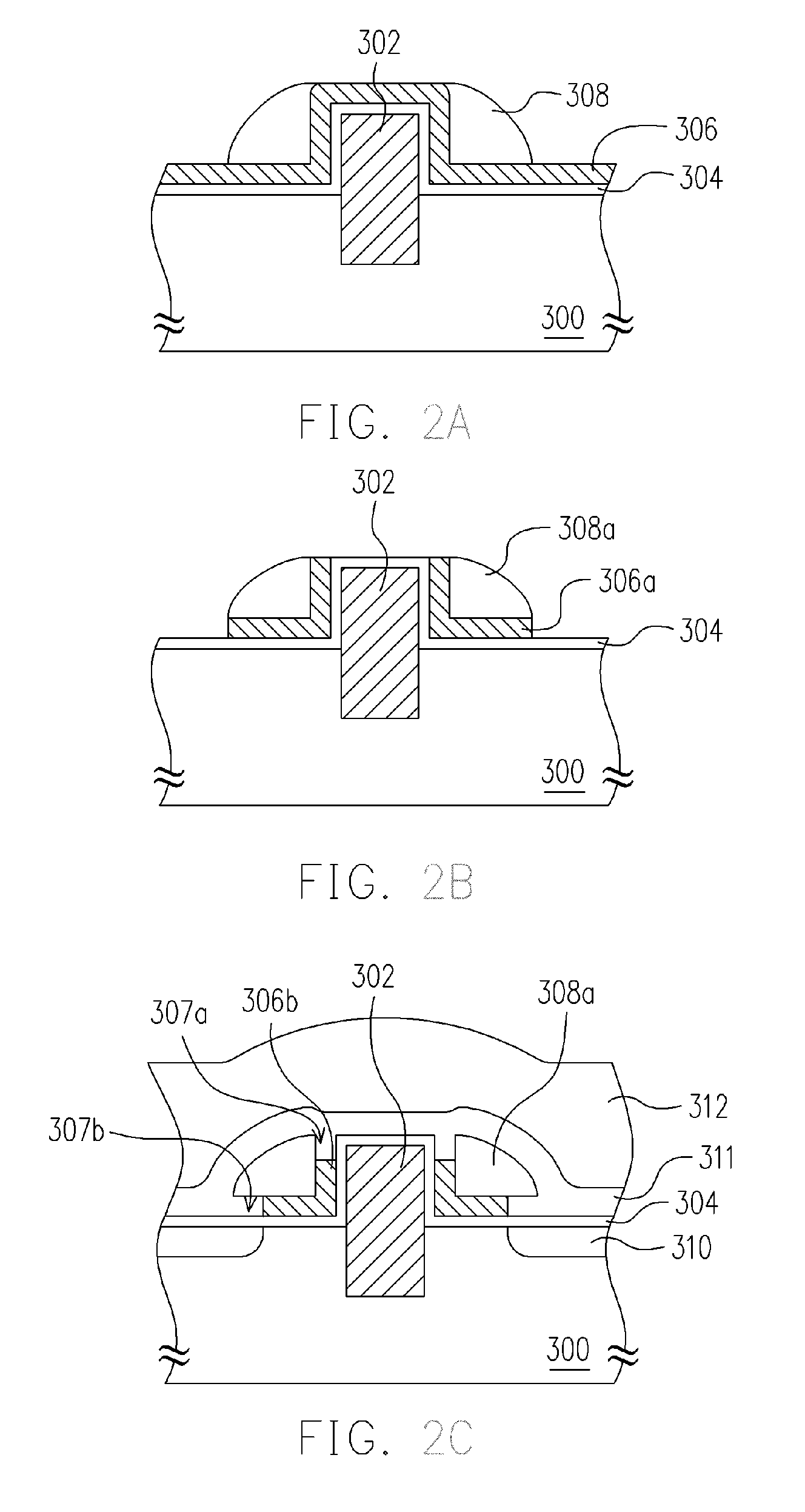
[0021]FIG. 2A to FIG. 2D are schematic cross sectional views showing the steps for fabricating a plug according to an embodiment of the present invention, wherein the plug is formed in the dielectric layer and is electrically connected to the trench type flash memory.

[0022]Please referring to FIG. 2A, a substrate 300 that includes the trench gate structure 302 is provided,...

second embodiment

The Second Embodiment

[0030]According to the present invention, the foregoing general description and the following detailed description of the embodiment with reference to the accompanying drawings are exemplary and explanatory for the fabrication of plugs during the interconnect processing. This invention, however, may be embodied in many different forms and should not be construed as limited to the embodiments set forth herein. The present invention is applicable to any process that is related to the formation of a plug in a dielectric layer, wherein the plug is electrically connected to an adjacent device underneath.

[0031]FIG. 3A to FIG. 3D are schematic cross sectional views showing the steps of fabrication of a plug fabrication in an interconnect manufacturing process according to another embodiment of the present invention, wherein the plug is formed in the dielectric layer and is electrically connected to the conducting structure at the lower level.

[0032]Please referring FIG....


PUM


Abstract

A method for manufacturing a semiconductor device is disclosed suitable for a substrate having a first conducting structure and a first dielectric layer, wherein the dielectric layer covers the first conductive structure. The method includes the steps of forming a second conductive structure over the substrate adjacent to the first conductive structure. Then, the size of the second conductive structure is reduced so that a top surface of the second conductive structure is relatively lower than that of the first conductive structure. Thereafter, a second dielectric layer is formed over the substrate to cover the first and the second conductive structure. A via is formed in the second dielectric layer to expose the top surface of the first conductive structure. Finally, a via plug is formed in the via.

Description

CROSS-REFERENCE TO RELATED APPLICATION[0001]This application claims the priority benefit of Taiwan application serial No. 94104420, filed on Feb. 16, 2005. All disclosure of the Taiwan application is incorporated herein by reference.BACKGROUND OF THE INVENTION[0002]1. Field of the Invention[0003]The present invention generally relates to a fabrication method of a semiconductor device. More particularly, the present invention relates to a fabrication method of a metal interconnect for a semiconductor device.[0004]2. Description of Related Art[0005]The higher the level of integration for integrated circuits, the smaller the semiconductor devices are being developed. Therefore, the size of the devices, for example, the width of the conducting line, the size of the gate, and the dimension of the plug shrinks to increase the level of integration. However, due to the miniaturizing of component devices, the difficulties in the manufacturing process greatly increase, and the demand for size...

Claims


Application Information

Patent Timeline
Patent Type & Authority Patents(United States)
IPC IPC(8): H01L21/3205H01L21/4763
CPCH01L21/76897H01L29/42328H01L29/66825
Inventor HUANG, MIN-SANCHEN, DAH-CHUANYOUNG, REX
Owner POWERCHIP SEMICON MFG CORP
Learn More