Filtering techniques for printhead internal contamination

a filtering technique and printhead technology, applied in printing and other directions, can solve the problems of reducing the service life of the printhead, affecting the design and cost of the printer, and preventing the flow of ink for high throughput images, so as to reduce the feature size and eliminate printing defects

Inactive Publication Date: 2003-09-30
HEWLETT PACKARD DEV CO LP
View PDF4 Cites 69 Cited by
  • Summary
  • Abstract
  • Description
  • Claims
  • Application Information

AI Technical Summary

Benefits of technology

Techniques are described for constructing filter type features capable of entrapping particle contaminants to eliminate printing defects. These designs utilize photo-imageable barrier material to fabricate various shapes and forms to reduce feature sizes. Several of these designs utilize secondary barrier material of height less than barrier materials used to fabricate ink feed channels and firing chamber walls. Another variation describes creation of a filter mesh from two layers of reduced height barrier materials.

Problems solved by technology

Increasing filter area can cause printhead size to increase, a detriment to printer design and cost.
With tighter nozzle spacing, large barrier islands spaced close together to trap small particles prevented adequate ink flow for high throughput images.
However, as nozzle diameters reduced in size smaller than the recommended barrier spacings and sizes, very small particles that pass through the barrier reef islands are trapped in the firing chamber / nozzle bore.

Method used


Image

  • Filtering techniques for printhead internal contamination
  • Filtering techniques for printhead internal contamination
  • Filtering techniques for printhead internal contamination

Examples


Embodiment Construction

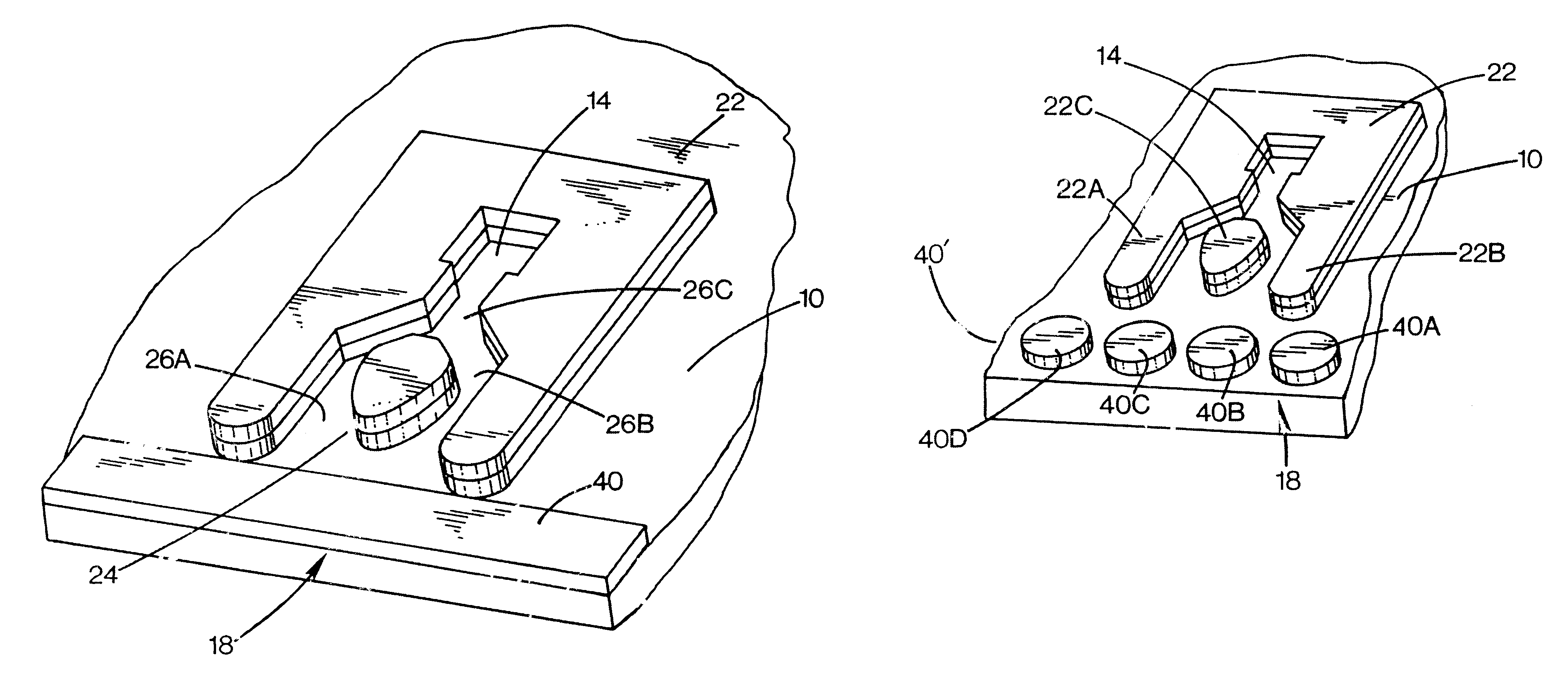
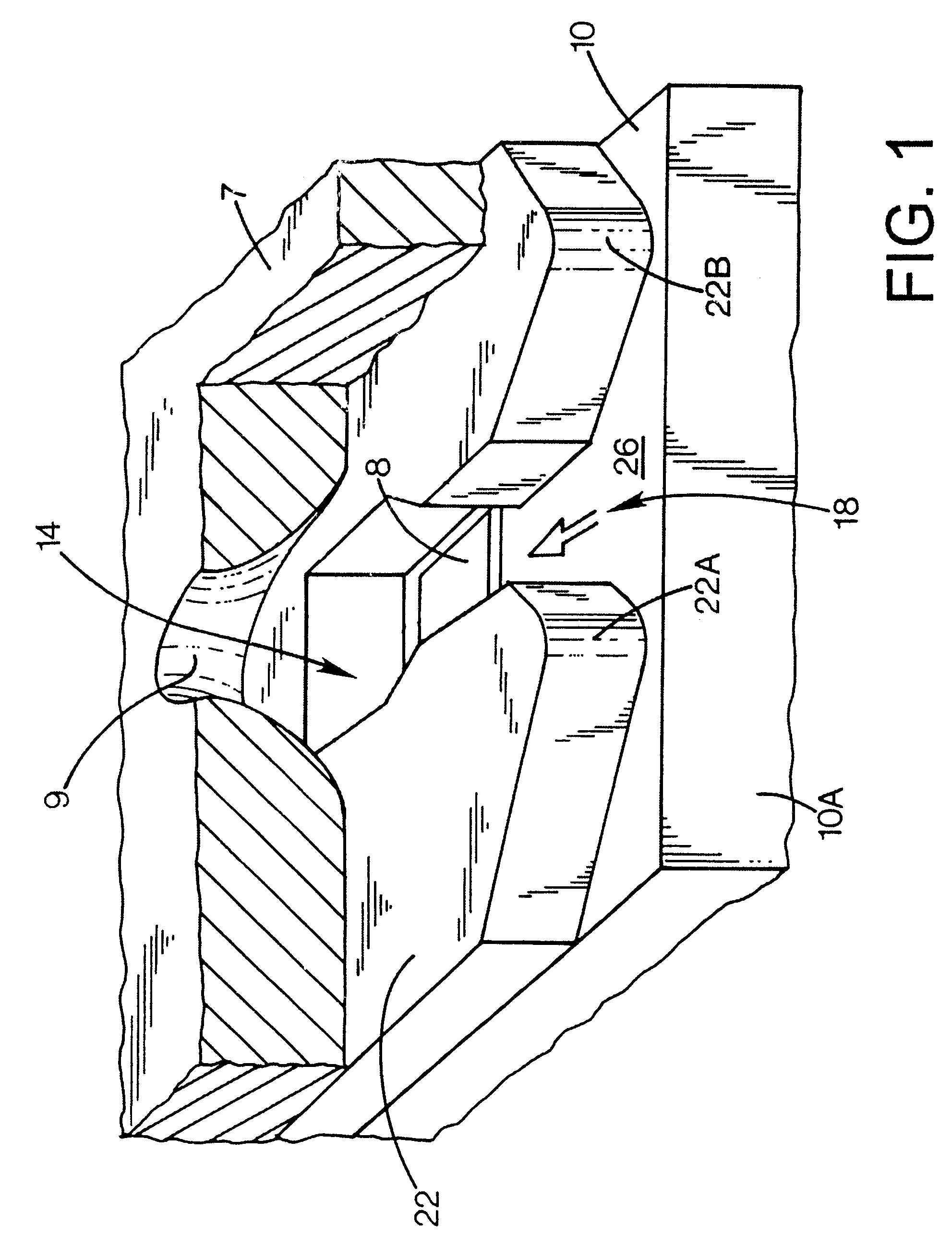
A magnified view of a portion of a typical thermal inkjet printhead for use in an inkjet printer is diagrammatically depicted in FIG. 1. The printhead includes a plurality of ink drop generators, each including a firing resistor, a firing chamber and a nozzle or orifice. Several elements of the printhead have been sectioned to reveal the silicon substrate 10, with a typical ink feed channel 26, firing chamber 14, and orifice 9 comprising a typical ink drop generator. Many such firing chambers are arranged in a group around an ink supply plenum for efficient refill of the firing chambers. Thus, associated with each firing chamber 14 is an orifice 9 formed in an orifice plate 7 disposed relative to the firing chamber 14 so that ink which is rapidly heated in the firing chamber by a heater resistor 8 is expelled as a droplet from the orifice 9. Ink is supplied to the firing chambers through an opening 26 called an ink feed channel. Ink is supplied to the ink feed channel from a much la...


PUM


Abstract

Techniques are described for constructing filter type features capable of entrapping particle contaminants to eliminate printing defects. These techniques utilize photo-imageable barrier material to fabricate various shapes and forms to reduce feature sizes. Several of these techniques utilize barrier material of height less than barrier materials used to fabricate ink feed channels and firing chamber walls. Another variation describes creation of a filter mesh from two layers of reduced height barrier materials.

Description

TECHNICAL FIELD OF THE DISCLOSUREThis invention relates to inkjet printheads, and more particularly to techniques for addressing internal contamination problems in printheads.BACKGROUND OF THE DISCLOSUREInkjet pens include a printhead comprising a plurality of orifices from which ink is expelled toward a print medium such as paper. Some pens include a reservoir of ink; others are connected to an ink supply through a fluid interconnect. A plurality of ink passageways exist between the ink reservoir and a plurality of firing chambers. Each such firing chamber includes a resistive heating element which is energized upon demand to expel an ink droplet through a nozzle orifice associated with that resistive heating element. The orifices are located on a surface such that the expulsion of ink droplets out of a determined number of orifices relative to a particular position of the medium results in the production of a portion of a desired character or image. Controlled positioning of the p...

Claims


Application Information

Patent Timeline
Patent Type & Authority Patents(United States)
IPC IPC(8): B41J2/14B41J2/175
CPCB41J2/1404B41J2/17563B41J2002/14387B41J2002/14403B41J2002/14467
Inventor RAPP, GERALD V.LASSAR, NOAH C.
Owner HEWLETT PACKARD DEV CO LP
Why Eureka
Try Eureka