Method for automatic frequency control

a frequency correction and automatic technology, applied in the direction of digital transmission, electrical equipment, transmission, etc., can solve the problems of high bit error rate, frequency offset presents a more significant problem, and receiver 20 cannot distinguish between phase changes

Inactive Publication Date: 2003-09-30
NOKIA NETWORKS OY
View PDF7 Cites 50 Cited by
  • Summary
  • Abstract
  • Description
  • Claims
  • Application Information

AI Technical Summary

Problems solved by technology

As is shown with specific regard to point A-E, while the real part of the signal remains constant, the phase of the signal changes relatively radically with time (represented by the z-axis). FIG. 5 illustrates the performance of a GSM system employing 8PSK modulation without any frequency correction which results in a high bit-error rate.
The frequency offset presents a more significant problem in a communication system, particularly in a system, device or product which has a high sensitivity to frequency error

Method used


Image

  • Method for automatic frequency control
  • Method for automatic frequency control
  • Method for automatic frequency control

Examples


Embodiment Construction

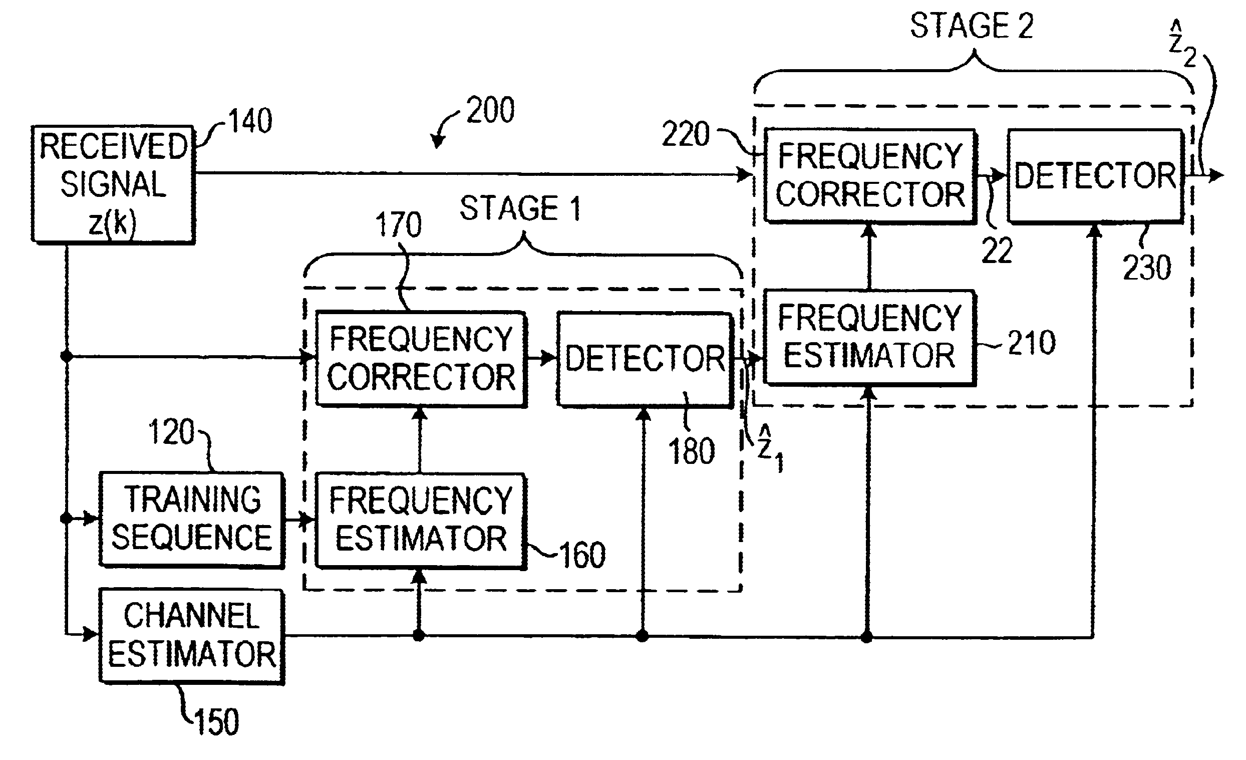
The frequency correction structure 200 of the present invention, shown in FIG. 8, improves upon the prior art by performing a two stage frequency correction, labeled Stage 1 and Stage 2. To distinguish between the values of variables calculated at each of the two stages, variables calculated at Stage 1 are denoted with a subscript 1 and variables calculated at Stage 2 are denoted with a subscript 2. Stage 1 is identical to the prior art DSP structure 135 of FIG. 6 and therefore the methods and appropriate calculations need not be repeated. In Stage 1, a coarse estimate of frequency offset .phi.=.phi..sub.1 is produced and the frequency correction that is performed results in an output z.sub.1 that is a vector containing a fairly accurate estimate of the detected bits without a significant amount of the frequency offset in the signal x(k). z.sub.1 includes the frequency corrected data symbols 110, 130 and the training sequence 120 in the burst that have already been frequency correct...


PUM


Abstract

A radio signal transmitted from a transmitter to a receiver of a mobile communications system, such as the GSM system, often suffers from a phenomenon known as frequency offset by which the frequency of the radio signal is changed from a first frequency to a second frequency. A method is therefore provided for automatically correcting the frequency at the receiver to restore the received radio signal to approximately the first frequency using a multistage frequency correction algorithm. The radio signal comprises a training sequence that is known to the receiver and data symbols that are not known to the receiver. In the first stage of the frequency correction, the frequency offset is coarsely estimated based on the training sequence only, and the data symbols are frequency corrected by back-rotating the received data symbols and the training sequence by the frequency offset estimate. The frequency corrected data symbols and training sequence are then input into the second stage of the frequency correction where they are used to determine a second estimate of the frequency offset that should be more accurate because the second estimate of the frequency offset is based on a larger number of symbols including symbols in the previously frequency corrected training sequence and data symbols. Using this second frequency offset estimate, the data symbols in the received radio signal are frequency corrected by back-rotating the received data symbols by the second frequency offset estimate and are output for detection.

Description

1. Field of the InventionThis invention relates to a method of automatic frequency correction of a received radio signal in a digital mobile communications system.2. Description of the Related ArtIn a digital mobile communications system, such as a GSM (Global System For Mobile Communication) system, data is transferred, referring to FIG. 1, between a transmitter 10 and receiver 20 as a radio signal over a physical channel which may use frequency and / or time division multiplexing to create a sequence of radio frequency channels and time slots. Typically, every frequency band is divided into many time division multiple access (TDMA) frames, with eight users per frame, each user being allocated time to send a single burst of information. The precise frequencies used vary by country. The physical channel over which the signal is sent is unknown to receiver 20. FIG. 2 illustrates a representative structure of receiver 20 in which the burst 30 is received by antenna 35, the signal is amp...

Claims


Application Information

Patent Timeline
IPC IPC(8): H04L27/233H04L27/00
CPCH04L27/2332H04L2027/0028H04L2027/0046H04L2027/0095
Inventor VAN DE BEEK, JAAPHEDQVIST, CHRISTERSTIGMER, PAR
Owner NOKIA NETWORKS OY
Why Eureka
Try Eureka