
Anti-theft product tag with ball clutch

Inactive Publication Date: 2003-10-14
FUSS ARTHUR +1
View PDF13 Cites 76 Cited by
  • Summary
  • Abstract
  • Description
  • Claims
  • Application Information

AI Technical Summary

Benefits of technology

Therefore, it is among the primary objects of the present invention to provide a novel two-component product protection device against theft or release by unauthorized personnel which includes a ball clutch mechanism permitting a restricted retention of the two components on an article or product and yet permits release thereof by authorized personnel.
Another object of the present invention is to provide a ball clutch mechanism for releasably retaining a pair of components together about an article or product intended to be protected against theft.

Problems solved by technology

However, should the first component with the pin be withdrawn by unauthorized personnel, the plug member will be pushed into the tapered recess of the housing by expansion of the spring and the balls will contract and restrict the shaft or pin member of the first component, so as to hold the component together.

Method used


Image

  • Anti-theft product tag with ball clutch
  • Anti-theft product tag with ball clutch
  • Anti-theft product tag with ball clutch

Examples


Embodiment Construction

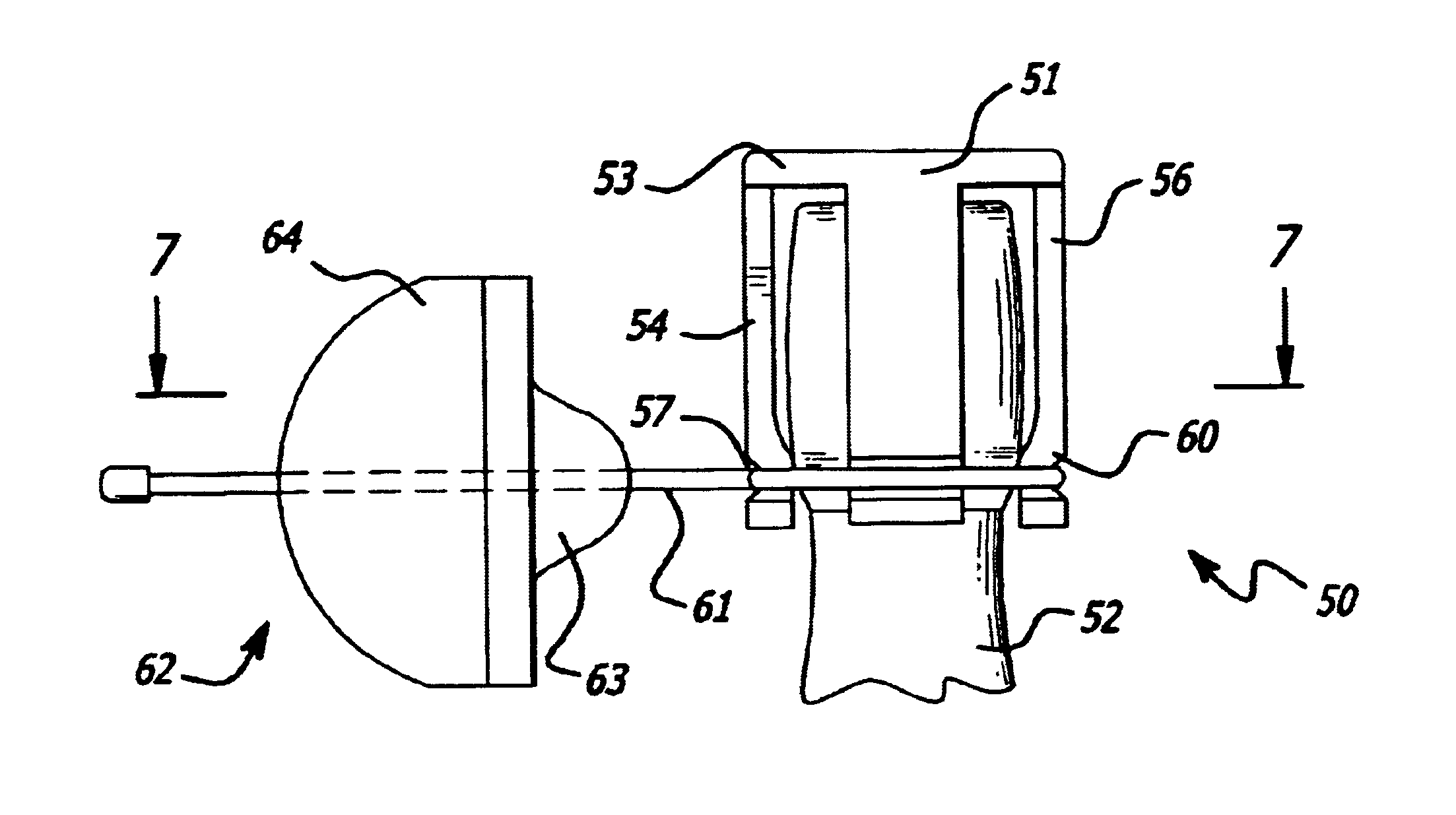
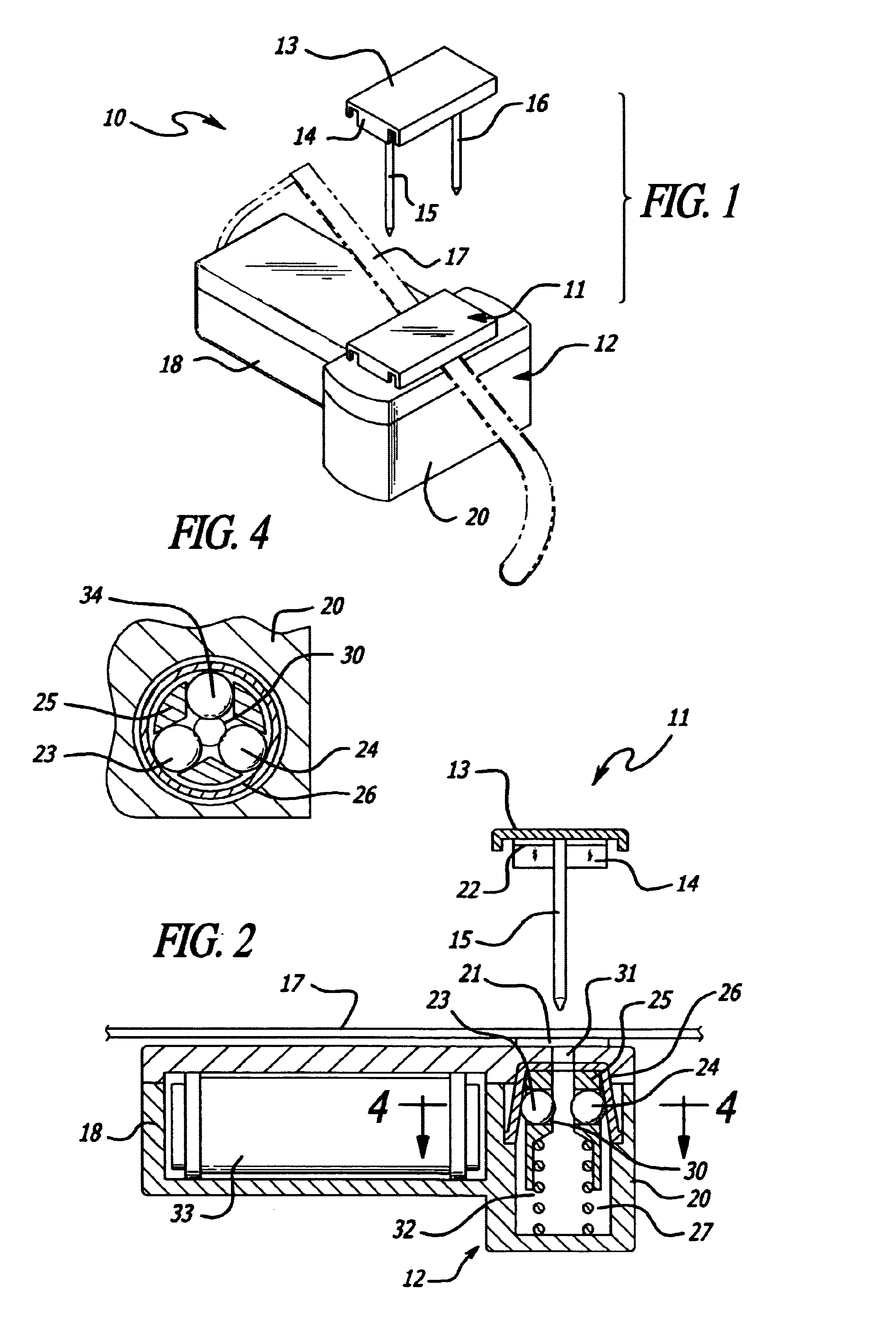
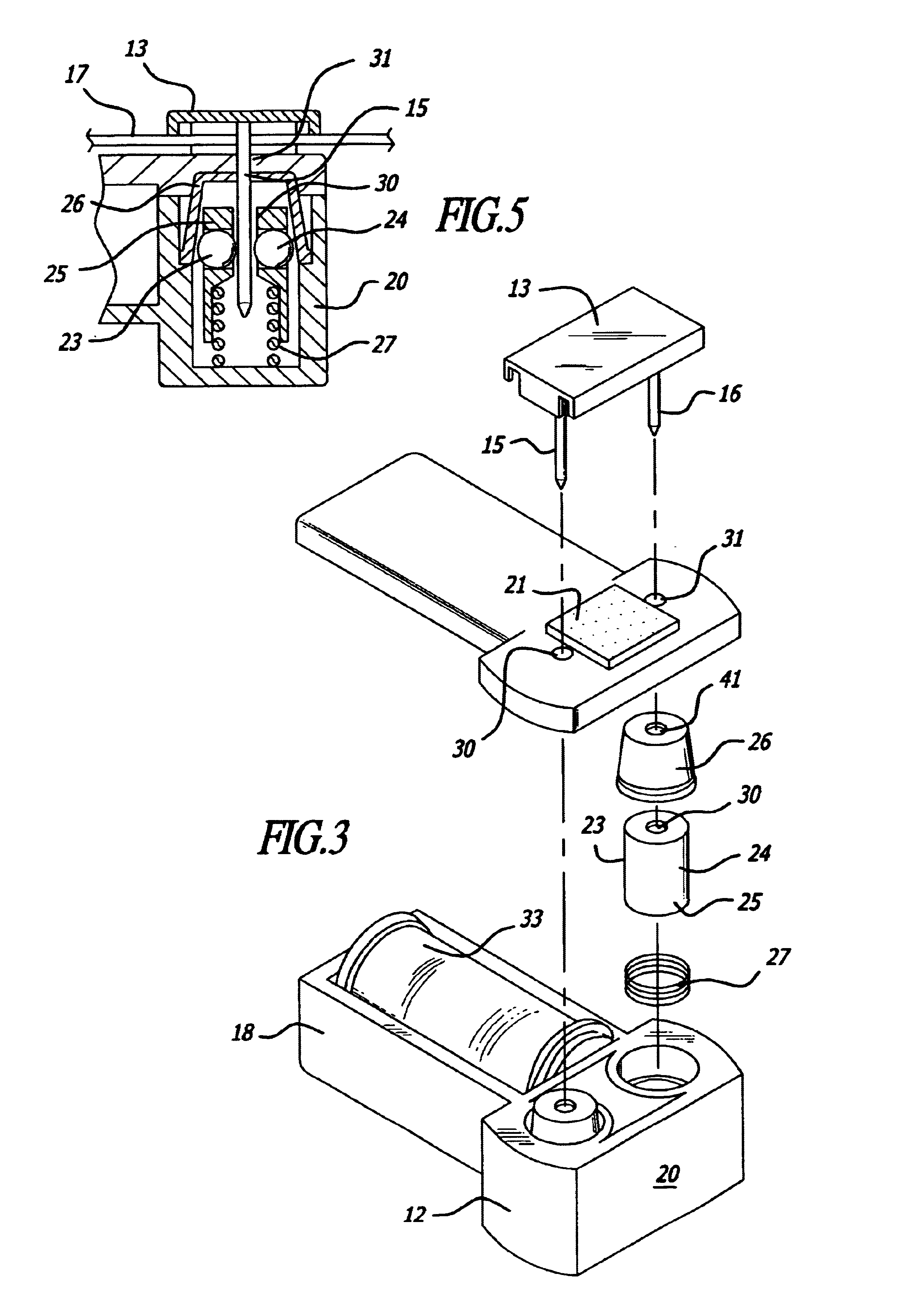
Referring to FIG. 1, the novel anti-theft tag or device is indicated in the general direction of arrow 10 which comprises a two-component construction wherein numeral 11 identifies one component which is detachably connected to a second component 12. The first component is illustrated in broken lines preparatory for connection with the second component 12 and the first component includes a housing 13 having downwardly depending continuous side 14 and further includes downwardly depending pins, shafts, prongs or the like. In the present instance, actuation members such as a pair of pins 15 and 16 are illustrated which are arranged in fixed, spaced apart relationship in order to provide a gap through which an item to be protected is disposed. For example, the ear pieces or arms of a pair of glasses such as indicated by numeral 17 may be placed between the pins 15 and 16 and the component 13 is then connected with the component 12 so that the product 17 is captured therebetween. It can...


PUM


Abstract

An article surveillance includes a pair of components that are detachably connected together having a releasably grasping device engaging with an article intended to be protected. The device is coupled between the two components with a selected one of the components having an elongated prong insertably received within the other component and is held thereto by a ball clutch mechanism. The mechanism includes a tapered housing with an internal tapered wall surface enclosing a plug member having at least two balls carried in opposing grooves. The tapered housing and the plug member include a coaxial passageway for insertably receiving the elongated prong from the first component. The plug member is resiliently biased to a first position by an expansion spring causing the balls to bear against the tapered inner wall of the housing, restricting the passageway. When the prong of the first component is occupying the passageway, the sides of the prong force the balls outwardly as the plug member moves to compress the spring. The widened mouth of the housing permits the balls to expand or separate and does not place any restriction on the pin. Should the first component with the pin be withdrawn by unauthorized personnel, the plug member will be pushed into the tapered recess of the housing by expansion of the spring and the balls will contract and restrict the shaft or pin member of the first component, so as to hold the component together.< / PTEXT>

Description

1. Field of the InventionThe present invention relates to the field of anti-theft garment and product devices and, more particularly to a novel tag adapted to be releasably secured onto a product intended to be protected from theft, wherein such a tag includes a ball clutch for securing and releasing a pair of tag components.2. Brief Description of the Prior ArtIn the field of product loss prevention, various tags have been provided which are detachably connected to garments and which are used to activate an electronic surveillance system including an alarm which would alert attending personnel. Such previous tags usually have one component which includes a transmitter while the other component is employed as a fastening component for joining the two components to a garment. Such practice has been successful in preventing theft of garments; however, a need has existed to protect products as well such as expensive eyeglasses, beverage bottles or the like. Garment tags rely on inserti...

Claims


Application Information

Patent Timeline
Patent Type & Authority Patents(United States)
IPC IPC(8): E05B73/00
CPCE05B73/0017E05B73/0035E05B73/0041Y10T24/50Y10T24/4607Y10T70/5566Y10T70/5004Y10T292/14Y10T292/11Y10T70/5031Y10T70/7057Y10T70/7751
Inventor FUSS, ARTHURXIAO, YANG
Owner FUSS ARTHUR
Learn More