

Liquid jet head and liquid jet apparatus
a liquid jet and apparatus technology, applied in the direction of printing, inking apparatus, etc., can solve the problems of affecting the ejection of liquid jets, affecting the manufacturing process of actuator plates, and air bubble accumulation in the nozzle holes, so as to and suppress the accumulation of air bubbles
- Summary
- Abstract
- Description
- Claims
- Application Information
AI Technical Summary
Benefits of technology
Problems solved by technology
Method used
Image

Examples
first embodiment
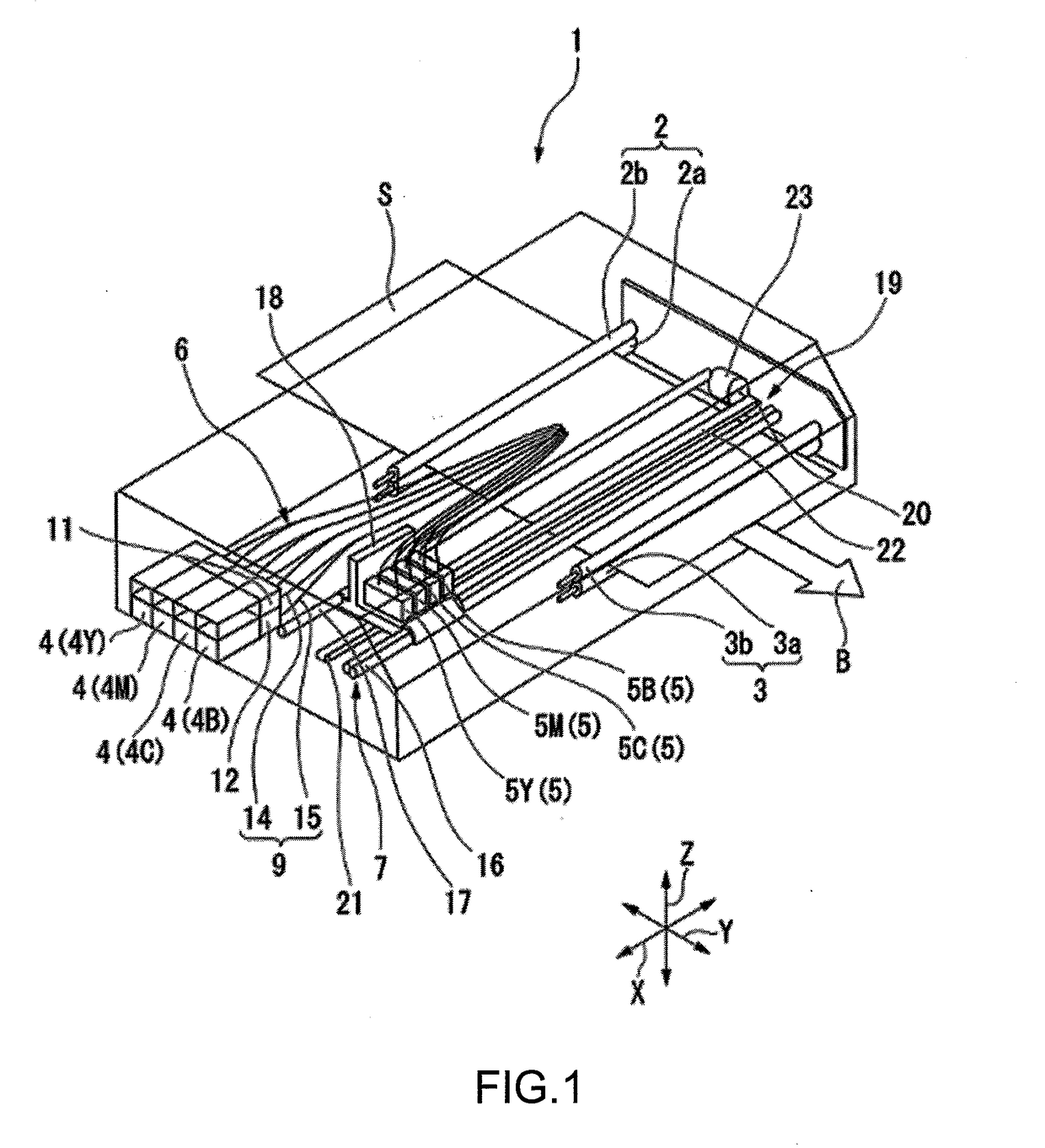
[0072]FIG. 1 is a schematic perspective view of a liquid jet apparatus 1 according to a first embodiment of the present invention. In FIG. 1, the scales of the members are changed as appropriate for the sake of understandability.
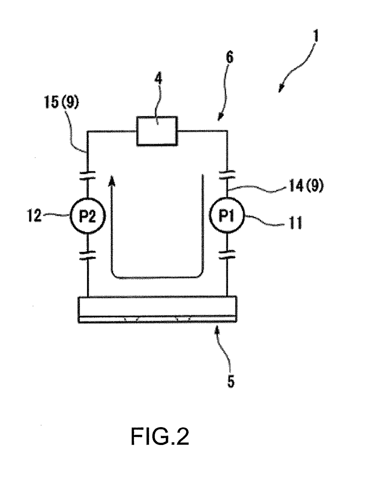
[0073]Referring to FIG. 1, a liquid jet apparatus 1 in a first embodiment includes: a pair of conveyance means 2 and 3 that conveys a recording medium S such as paper; an ink tank 4 that stores an ink, a liquid jet head 5 as an ink-jet head ejecting ink droplets onto the recording medium S; an ink circulation means 6 that circulates the ink between the ink tank 4 and the liquid jet head 5; and a scanning means (movement mechanism) 7 that moves the liquid jet head 5 for scanning in a direction (direction along the width of the recording medium S (hereinafter, called X direction) orthogonal to a direction of conveyance of the recording medium S (hereinafter, called Y direction).
[0074]Z direction (vertical direction) in the drawing indicates a height direction ...
second embodiment
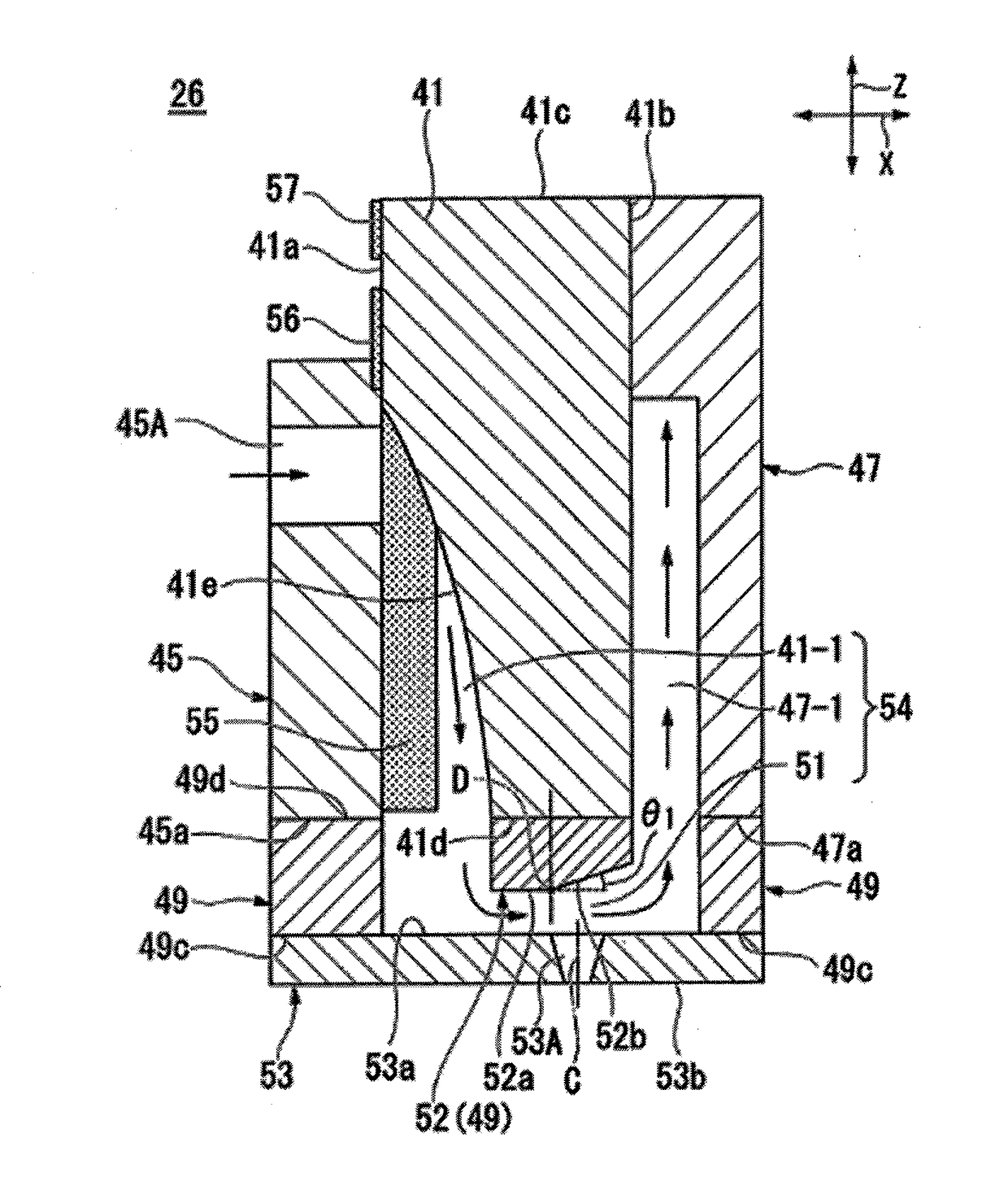
[0153]FIG. 6 is a cross-sectional view of main components of a head chip according to a second embodiment of the present invention. FIG. 6 is a cross-sectional view of a head chip 60 in the second embodiment sectioned to pass through the ejection groove 41-1 as with FIG. 5 described above. In FIG. 6, the same components as those of the head chip 26 illustrated in FIG. 5 are given the same reference signs as those of the head chip 26. FIG. 6 does not illustrate the common electrode 55, the common terminal 56, the individual terminal 57 illustrated in FIG. 5 and the active electrode constituting the head chip 60.
[0154]Referring to FIG. 6, the head chip 60 of the second embodiment is configured in the same manner as the head chip 26 described above in relation to the first embodiment except in including an air bubble retention suppression unit 61 instead of the air bubble retention suppression unit 52 constituting the head chip 26 and having a side flow path 51 different in shape from ...
third embodiment
[0162]FIG. 7 is a cross-sectional view of main components of a head chip according to a third embodiment of the present invention. FIG. 7 is a cross-sectional view of a head chip 70 in the third embodiment sectioned to pass through the ejection groove 41-1 as with FIG. 5 described above. In FIG. 7, the same components as those of the head chip 26 illustrated in FIG. 5 are given the same reference signs as those of the head chip 26. FIG. 7 does not illustrate the common electrode 55, the common terminal 56, and the individual terminal 57 illustrated in FIG. 5 and the active electrode constituting the head chip 70.
[0163]Referring to FIG. 7, the head chip 70 of the third embodiment is configured in the same manner as the head chip 26 described above in relation to the first embodiment except in including an air bubble retention suppression unit 71 instead of the air bubble retention suppression unit 52 constituting the head chip 26 and having a side flow path 51 different in shape from...
PUM
 Abstract
Description
Claims
Application Information